|
|
Post by JohnH on Feb 24, 2012 16:13:38 GMT -5
I thought Id just check if I could really do the BS that I offered yesterday, in terms of tweaking the op-amp circuit tone. Here is a couple of versions: (note in the sim model, the + input is referenced to ground rather than 4.5v, but this makes no difference to this test) Bass BoostBy adding a resistor and capacitor at the input to cut higher frequencies, and then adding gain in the feedback lop, a bass boost can be created:   Bass and high boost Bass and high boostSame thing, with a further R and C in the feedback loop, to reduce feedback at higher frequencies and so boost them – hence resulting in an overall mid dip:   So this seems to confirm that the op-amp circuit can be quite effective at tone shaping. Actual values will depend on results required. John (BTW Just for discussion - here’s where I would go with this, if it was my guitar: Passive volume control after the mag pickup JFET buffer for the mag pu Tone- adjusted op-amp buffer for the piezo 500k blend pot followed by JFET output buffer Current draw about 1.6mA) |
|
|
|
Post by darkavenger on Feb 24, 2012 19:08:51 GMT -5
BTW Just for discussion - here’s where I would go with this, if it was my guitar: Passive volume control after the mag pickup JFET buffer for the mag pu Tone- adjusted op-amp buffer for the piezo 500k blend pot followed by JFET output buffer Current draw about 1.6mA) Ok, so add a JFET buffer after the blend. How about if I added a blend pot that was separate from a passive volume. Would that change the pot value? I'm not sure what's going on here. This can NOT be right, but I just tested the current draw for my circuit. Apparently, this circuit only consumes 0.09mA!!! For a curveball, I'm not using a TL071 but rather a LT1351. Still, the data sheet says current draw should be 0.25mA/250uA. I think I need a little help here. www.linear.com/product/LT1351Edit for proof. 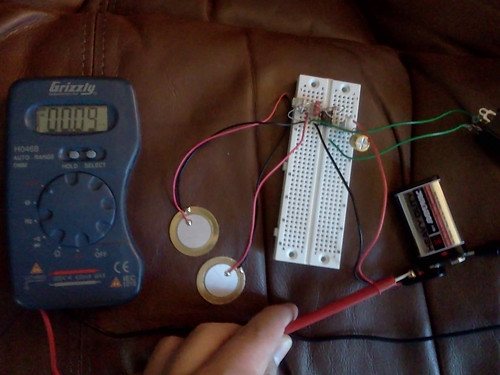 |
|
|
|
Post by JohnH on Feb 24, 2012 19:35:27 GMT -5
Not sure how you mean with the valume control. There are lots of ways that might be done and issues that arisethat we went through with 4real, so I suggest ploughing through his thread! Setting aside the electronics, how do you want the knobs to operate?
Just on the current draw - thats good news! It seems very suitable for a battery powered circuit, a much newer design than the TL071. Id expect actual measured current could be different from the max values in the spec sheets.
J
|
|
|
|
Post by darkavenger on Feb 24, 2012 20:04:54 GMT -5
Well... wow. The current draw is incredible. I was under the impression a JFET buffer would take more power than that? How long would it run on a typical 9V?
I can't seem to figure out a way to use the blend pot as a volume. So if I add in a new blend pot, say 100k as used in others projects, would this be good to get a fully mag, good blend, and fully piezo sound?
Edit: I think I might try out the bass and high boost. What is the advantage of cutting the highs before the op amp and then boosting them after? Could that be done just in the feedback part?
|
|
|
|
Post by JohnH on Feb 25, 2012 15:57:45 GMT -5
I was just experimenting with what could be done. You can try those eq tweaks but there's no advantage to them unless they help get you a tone that you like. In my case, i needed to create a mid dip to get a better tone, but you may not, or maybe need some other adjustment.
Ive also had trouble keeping a simple circuit but with control of volume. That's why I just have the passive mag volume before the buffer and the blend. If I want all mag, I set the blend to full mag and adjust volume with the mag volume pot. If I want all piezo, I turn the mag volume to zero, and now the blend acts as a volume pot for the piezo. If I want some of each, I set the main one and then adjust. With those two controls I can get any blend at any volume. And if you want a passive mag-only output, the mag volume is there to control it.
On the op-amps, with that low current, you could indeed use them instead of JFETs if you wish, depends what you are comfortable with. (I have a bag of JFETs so I use them for everything)
|
|
|
|
Post by darkavenger on Feb 25, 2012 20:23:47 GMT -5
Ok, I'm going to replace the bridge, well, fairly certain anyway. In the mean time, I'll mount the piezos under the existing bridge and get some recordings. It won't be a perfect reflection of my setup when I'm done with everything, but it'll be fun anyway. Look for a post by tomorrow morning or possibly later tonight, I'll have some more free time to get everything setup.
|
|
|
|
Post by reTrEaD on Feb 26, 2012 11:44:25 GMT -5
How long would it run on a typical 9V? Define "typical". Zinc-carbon is cheap but has less capacity. Alkaline is reasonably priced, and is generally the "standard" choice. Lithium has a much longer life in low-current applications, but is quite pricey. Expect a little over 550 mAh from an alkaline battery. Divide the capacity by the current (in miliamps) to determine the lifetime in hours. Ive also had trouble keeping a simple circuit but with control of volume. That's why I just have the passive mag volume before the buffer and the blend. If I want all mag, I set the blend to full mag and adjust volume with the mag volume pot. If I want all piezo, I turn the mag volume to zero, and now the blend acts as a volume pot for the piezo. If I want some of each, I set the main one and then adjust. With those two controls I can get any blend at any volume. And if you want a passive mag-only output, the mag volume is there to control it. This is a little more complicated to manage than having blend before volume. But it's very "economical" from the standpoint of number of controls and switching. You could accomplish this with just one pole, if you don't mind leaving the input to the mag buffer connected when in passive mode. If you use a second pole to disconnect the buffer from the wiper, it could also connect a treble bypass network. Add a third pole, if you want to switch the battery off when in passive mode. If the mag buffer is connected to the raw signal before the volume control, it would take two poles to move the volume control to the middle of the active circuits. A third pole to move the output jack from the passive to active system. And a fourth pole if you wanted to disconnect the mag buffer input. And a fifth pole if you also wanted to turn off the power when in passive mode. You could get by with less switching if you had a volume control for the passive mode and a separate volume and blend for the active mode. That might be a bit confusing to use. But using a ganged pot for the volume would eliminate that problem. |
|
|
|
Post by JohnH on Feb 26, 2012 14:23:02 GMT -5
On battery life, 550mAH is also what I have read for an alkaline. But I believe they rate it that way by draining it until voltage is halved, which is too low for our circuits. So I reckon on about 300mAH, so 300 hours if you use 1mA of current.
|
|
|
|
Post by darkavenger on Feb 26, 2012 14:37:55 GMT -5
Preliminary recording: www.soundclick.com/bands/default.cfm?bandID=1236245Having problems mounting the things, so just stuck it behind the bridge on the string again. I also added a 10db amplification in audacity. Edit: Trim pots are set to 500ohm and 1meg, cap is 4.7nf/4700pf I'll also have a 2.2nf cap 0.09mA with 300mAh is 3333 hours. I've seen 550mAh too but it never seemed right, just wondering how you calculated it. Now I know! Double Edit: Had success with the piezo under bridge thing. Added an mp3 with some chords and stuff, but the cable cut out in the middle so I removed the end. When I get everything mounted properly I think the string levels will level out a bit. This is fun! Also, in the second song I adjusted some things, swapped cap for 2.2nf which is better, dropped trims to about 750k and 230ohm. It REALLY needs to be shielded, but I'll just deal with it for now(testing) Triple edit: I think something was shorting or something, I got a lot of the fuzz out of the sound now. 2.2nf still sounds right, I think it might be too much gain but it still sounds good. The 1 meg trim sounds good at about 300k to 500k and starts loosing a little treble after that and starts sounding more like a magnetic pup. Also, when I touch some of the resistors I can hear one of the local radio stations through my amp. I think it's time to hone in on some settings, I'll try to get some more direct recordings up tonight. 4th and FINAL edit: I added a better sample to analyze, piezo2.mp3. The only thing I adjusted was the 1 meg trim, strum 1 is 1 meg, strum 2 is about 500k, and strum 3 is... probably 200k? Anything under 100k doesn't come through. I also used a 4.7n and 2.2n cap in parallel for this one, just playing around. The range of tones you can get from this thing is pretty incredible.... I'm thinking about changing the trim pot to a normal pot because it seems to be the most useful control. Maybe a dual gang pot could add in a bit more... this is really, really fun. |
|
|
|
Post by reTrEaD on Feb 26, 2012 20:26:47 GMT -5
On battery life, 550mAH is also what I have read for an alkaline. But I believe they rate it that way by draining it until voltage is halved, which is too low for our circuits. So I reckon on about 300mAH, so 300 hours if you use 1mA of current. John, that's a very conservative estimate. The good thing about conservative estimates is that any surprise are usually good surprises. The source-follower jFet buffers you have tend to act like fixed resistors. When the battery voltage droops, the idle current also decreases. It's true that they run their tests out to where the battery voltage is half the rated value. But that part of the curve is fairly short, and accounts for little of the total mAh spec. When the battery voltage drop, the current it's supplying is also reduced. If you do your estimates based on the current drain at 9v, this will take you to where the battery voltage has dropped to 7v. You won't have actually used the total charge (550 mAh) because the actual current is less than the estimated current for most of that time. Even with a constant current discharge, the lifetime is only about 10% less than expected when the voltage drops to 7v. 208.173.184.182/oem/Pdf/Mn1604.pdf |
|
|
|
Post by darkavenger on Feb 26, 2012 20:37:05 GMT -5
So that weighs in closer to 5000 hours, plus a bit... if used constantly. wow...
I like the edit button: My cheap breadboard is broken, that's why nothing under 100k was coming through. I changed the pin to a another spot and it works. It sounds very light, very acoustic like. The higher the value of the 1 meg trim the less 'acoustic' it sounds, but not necessarily in a bad way. again... this is fun.
|
|
|
|
Post by JohnH on Feb 27, 2012 14:21:57 GMT -5
I had a listen to the recording, and the sounds are quite promising. I couldnt download them though.
How was the recording done? If its a direct recording, then I think Id be looking for a few more high harmonics to make it more acoustic sounding, but its within range of being good.
|
|
|
|
Post by darkavenger on Feb 27, 2012 21:10:11 GMT -5
www.soundclick.com/util/downloadSong.cfm?ID=11470364This should be a direct link to my new sound file. Breakdown: Intro is showing shielding/insulation problems. This will be fixed in the final version. Also tapped on the guitar, first on the bridge, then the back, then the headstock. 4.7 + 2.2 cap parallel Strum 1 - trim is about 200k(a guess) 2 - half way (500k) 3 - full (1meg) 4.7 cap 4 - full 5 - low 2.2 cap 6-low 7-full I left a gap in the audio between the cap changes for reference. Sorry for the clipping at higher gains!
|
|
|
|
Post by JohnH on Feb 28, 2012 14:36:11 GMT -5
I downloaded the new sample, and I think there is scope for getting a better sound with EQ, but gotta run now . Do you think you will be able to avoid that 60hz hum?
|
|
|
|
Post by darkavenger on Feb 28, 2012 18:22:18 GMT -5
Absolutely, piezos are somewhat notorious for picking up interference. Right now, there is no shielding and little insulation between the bridge and piezos... not a good combination, but I was able to get it working so purpose served. I've been trying to think of the best way to shield them, mostly for appearance's sake, so that should be the next step. Edit: Amazing how much some quick and simple shielding improves things. This isn't even completely shielded! www.soundclick.com/util/downloadSong.cfm?ID=11472549Edit2: Would you mind helping me out with 5spice? I tried to setup up a simulation but I don't think it worked the way it was suppose to. When I built the charge amp it failed, and I tried your circuit but got similar but different results, I used 2.2nf and 750k in the feedback loop. |
|
|
|
Post by darkavenger on Mar 2, 2012 14:57:51 GMT -5
Update: I've refined some values in the circuit and added a recording. The feed back trim pot is now a 500k linear pot and the output trim resistor is set to near 100 ohms. The lowest useable resistance in the feedback loop seems to be about 47k so I'll add a resistor to the pot in the final version to eliminate the dead spot. I've also noticed a slight volume increase as the feedback resistor increases in value, I'm wondering what could be done with a dual gang pot to adjust? Download www.soundclick.com/util/downloadSong.cfm?ID=11479356 |
|
|
|
Post by JohnH on Mar 2, 2012 16:23:53 GMT -5
I like the first strum, which I reckon would mix well with a bit of mag pup to thicken it. What is the cap in the feedback loop now set at, and also, are your piezos in series or parallel (or is it a single piezo). If I can understand all the current values, Ill run you a 5spice model to show how the feedback pot is affecting the output (as a bass cut control I think)
I do suggest getting some reference with a magnetic pickup sooner rather than later, because if you need to change the gain, the component values or tones will all be different. Do you have another guitar with a pickup that is somwhat similar, or (maybe you know it to be a bit more or less powerfull), so you can record that at the same settings? It would be a shame to find that the piezo is being fine tuned to a level which is several times different to what you will want to match a mag pup. Im not saying thats the case, but just thought Id mention it.
|
|
|
|
Post by darkavenger on Mar 2, 2012 19:12:52 GMT -5
 This is a somewhat accurate representation but you'd need to replace the feedback resistor with a 500k linear pot. The piezos are wired in series and should be about 9nf (+/- 2nf) I'm pretty happy with the variation I'm getting in the sound via feedback resistance, but it could be improved a little bit further. I know it would be ideal to have a mag pup to compare to and the piezo isn't even installed as it will be, but I'd like to learn how to analyze what's going on and a bit about how to manipulate it. |
|
|
|
Post by JohnH on Mar 2, 2012 22:32:40 GMT -5
From your diagram, looks like you may already have an analysis model set up? Anyway, here is a plot from my version of your circuit, using the current values, with the feedback resistor swept from 50k to 550k (ie, its a 500k pot with a 50k resistor in series)  Quite a useful control, if the max bass is a bit boomy and you'd like to be able to trim it. If you are interested in another knob, you could also have a presence control, to enhance high-end acoustic zing. This is done with an extra 10k pot in the loop (R7 above), with a cap to keep it from getting too extreme:   The two controls could work together if wanted John |
|
|
|
Post by reTrEaD on Mar 2, 2012 22:50:19 GMT -5
From your diagram, looks like you may already have an analysis model set up? Apparently he has a model, but his is missing a very important part. The capacitor to represent the internal capacitance of the piezo element. The feed back trim pot is now a 500k linear pot and the output trim resistor is set to near 100 ohms. The resistor in series with the output (R7) is a non-critical value. Its only function is to protect the opamp in the event of a short circuit. |
|
|
|
Post by JohnH on Mar 2, 2012 23:04:50 GMT -5
Apparently he has a model, but his is missing a very important part. The capacitor to represent the internal capacitance of the piezo element. Good point, and I included it in my models, at 9nF. the interaction of that with the components in the feedback loop is crtical to it working at all. The feed back trim pot is now a 500k linear pot and the output trim resistor is set to near 100 ohms. Yep, so I didn't model the output components. |
|
|
|
Post by darkavenger on Mar 3, 2012 0:17:32 GMT -5
So I figured I'd have to be making my own dual gang pot if I want to keep knobs to a minimum, and this is what I've come up with so far!  I figure the second pot(the wheel) can be epoxied to the first opened one and that second pot can control the start and end of the turn since the two turn around the exact same amount. The other option I was considering was to get a dual gang pot and try to switch parts out, but that would have to wait till I need enough parts to make an another order. I've added a 9nf cap to comp for the piezo's capacitance, THANKS! I got it working! I guess I forgot to add that back in... I removed it because I was trying to duplicate JohnH's previous work and I miss wired the bass boost and removed it. I hope you don't mind me using your work to try to get a baseline, I've never used spice before and I'd have no idea if I was even doing it right otherwise. The presence control might be exactly what I was looking for. Now that I know I have a working model, I'll play with a few things and see what happens. I think I'm going to be learning a lot more about active electronics in the near future. Hopefully I'll be able to get a few simulations posted and you guys can help point out what I'm doing wrong. As always, ANY suggestions, comments, opinions, etc. are always welcome. I've uploaded my model here if you'd like to play with it, sorry if it's sloppy. SCH file www.mediafire.com/?khb56np53irgsx6 |
|
|
|
Post by JohnH on Mar 3, 2012 1:50:39 GMT -5
I got your model running - are you getting results from it now? If not, make sure you have all the required parameters sepcified, see these screens, from the analyze, select/edit tab:   |
|
|
|
Post by darkavenger on Mar 3, 2012 22:11:08 GMT -5
Ok here is a little something. I tried a few different setups, most of them didn't have much effect, but I think this might be on the right track. I added in what would be a dual gang pot as I described with a 500k and 10k resistance. They are wired opposite so when the first is 500k the other is 0. I added this 10k pot at the beginning wired in parallel with a 22nf cap so that there is a mid boost with the bass boost. I may have to re-evaluate this after the piezo is remounted. 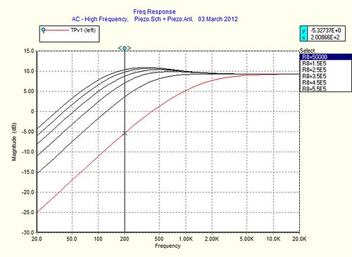 So far I haven't had as much time to play with it as I'd like but I've been learning more about active electronics too! |
|
|
|
Post by JohnH on Mar 3, 2012 22:23:17 GMT -5
Just a small observation: I only see R8 being varied there, as shown by the box on the right. Did you intend the extra 10k also to be swept in value? which is possible if you click both sweep1 and sweep2 boxes ,
|
|
|
|
Post by darkavenger on Mar 3, 2012 23:57:25 GMT -5
Yes, I forgot to check that box... it looked a little better when I did. What is your take on how this might sound? It's basically your presence circuit with a few tweaks, I swapped 5nf caps for both caps in the feedback loop and I added a 2k resistor in series with the 10k pot. Still wired reverse.  |
|
|
|
Post by JohnH on Mar 4, 2012 0:48:38 GMT -5
I think that could sound good. I just tried adding the rough amount of prescence boost that the graph shows, to your third strum from the recent recording. It adds a bit more acoustic edge, which is nice. I think it would be good with two knobs, but if you only want one tone knob though, how about having a preset resistor, say 50k, across the 10k pot so you can dial it down if needed - you might want to change the balance between bass cut and high boost.
J
|
|
|
|
Post by darkavenger on Mar 4, 2012 1:48:08 GMT -5
That sounds good! How do you propose lowering the bass? I want to play with it to figure it out, I might have some more time tomorrow. I noticed that the bass cuts in a bit too quickly as you add resistance to the 500k pot, I changed it to 250k and it looks better. I also went back to two 2.2nf caps to keep the treble boost higher. 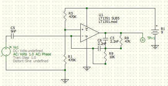  |
|
|
|
Post by JohnH on Mar 4, 2012 2:24:18 GMT -5
That seems to be cutting more bass, with a 250k pot - probably best to test it on the actual circuit to see if you like it. Gain is rising too, so watch your recording and amp input levels.
|
|
|
|
Post by darkavenger on Mar 4, 2012 15:11:13 GMT -5
I think this should be about right. I think that a 250k pot plus 47k in series will allow enough power in the bass to come through without loosing much other than an increase in volume. I'm also using 3k in series with the 10k pot. I'm going to try it out and see how it sounds, look for an edit with sound file!  Edit: I like the sound from presence control! Unfortunately I think it's time for a mouser order again because I need another 2.2nf cap, among other things. The 5nf cap is not enough to boost the twanginess of the treble like the 2.2nf cap does and it really dampens the whole thing. I've noticed from tweaking the model that the second cap tends to 'look' more effective when it's just slightly lower than the first, this simulation is 2.2nf followed by 1.8nf. The gain is starting to get pretty high, but I'm not sure it's such a bad thing in the treble, thoughts? I'll upload a sound file by the end of the day. 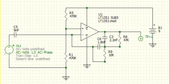 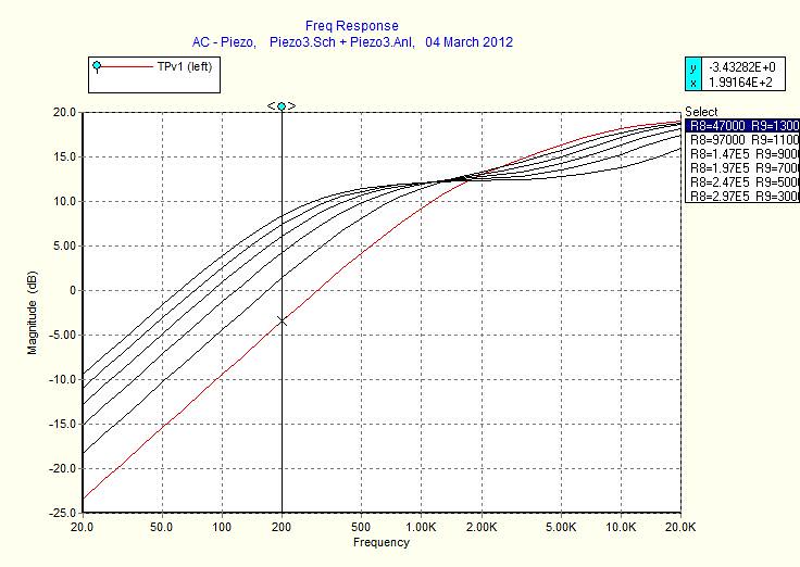 Also, 4.7nf followed by 1.5nf, but might still lack high end a little. 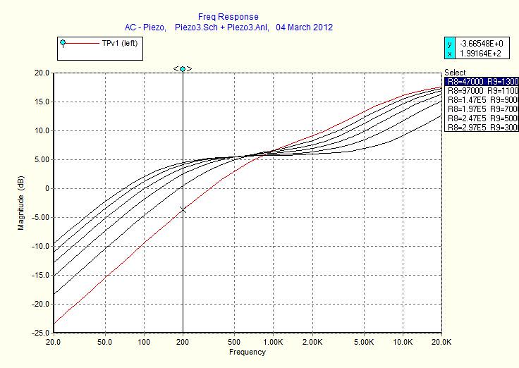 Any suggestions on anything else I might want to pick up from mouser while I'm making an order? I'm thinking about grabbing a few inductor to play with, they seem like they might be interesting. So far I'm getting a 4pdt switch, 100k and 250k linear pot, 4.7nf, 2.2nf, 1.8nf, 1.5nf caps for this project. |
|