bmic1980
Rookie Solder Flinger

Posts: 14
Likes: 0
|
Post by bmic1980 on Apr 12, 2012 23:16:44 GMT -5
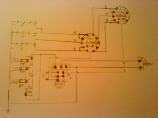
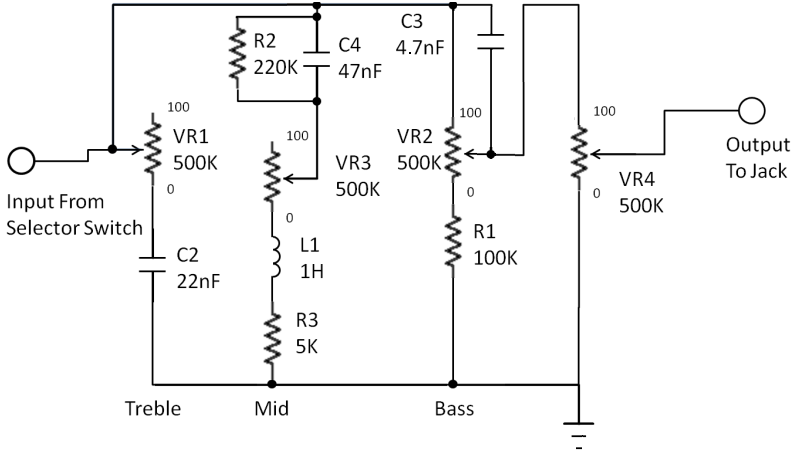
Here's hoping the pool is full of water, I'm jumping in head first... I've had a Chinese Squire laying around for a couple of years after some friends of my wife gave it to us. Body only needs a little work and a refinish and the neck is in good condition. the hardware and OTOH, having set inside a storage room without a case, left just a little to be desired. I'm finally sitting down rebuild this Strat into something far more than what it started as. My base concept for wiring this guitar starts with John Atchley's Double Barrel Switching , but rather than a master volume and master tone, I wanted more. I wanted to add a passive distortion circuit as discussed in the modules threat guitarnuts2.proboards.com/index.cgi?board=modules&action=display&thread=4787 and either do three individual tones, or a passive three band EQ as being discussed here guitarnuts2.proboards.com/index.cgi?board=wiring&action=display&thread=6220. For my electronics hardware, I'm using a Seymour Duncan "Everything Axe" Set www.seymourduncan.com/products/electric/sets/everything_axe/, a Schaller Megaswitch S and a Superswitch for switching duties, A single 500k pot for master volume, a 500k/500k stacked concentric pot for Neck/mid Tone or Treble/Mid EQ, and a 500K/250K for Bridge Tone/ Passive Distortion or Bass EQ / Passive Distortion. Now here is where I turn to you all for your wisdom. Below I have images posted my best concepts at a wiring diagrams for both options with my best guess at an schematic for the EQ circuit as discussed in the aforementioned thread. The layout images came courtesy of this board and Chris K, and all wiring layouts were done in PowerPoint (I'm sure there are far more efficient methods, but I'm familiar with it and could manipulate things the way I wished). Notes on the Wiring Diagrams, wires are color coded with bridges used when crossing wires of the same color. Wiring point junctions were used where wires joined, either of the same or different colors. I hope they are fairly easy to read... Layout One: Individual Tones, likely the easier of the two to complete. 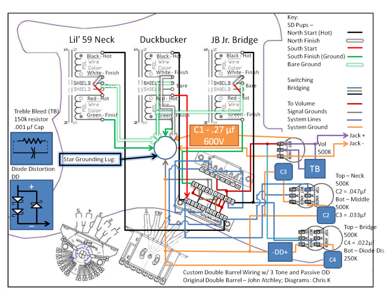 Layout two: 3 Band EQ, likely more difficult, but that's what makes it fun 3 band EQ schematic: 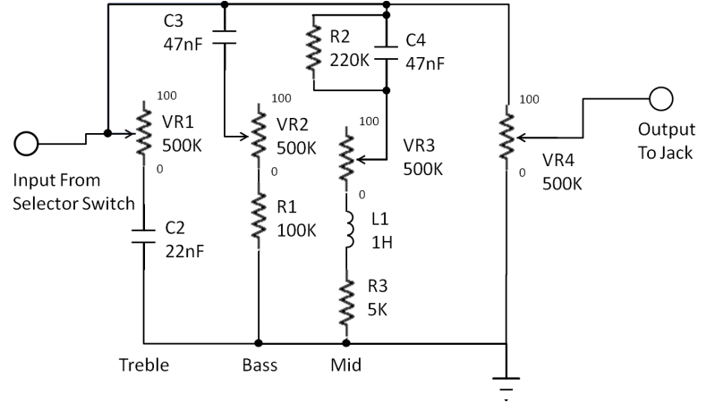 Diagram 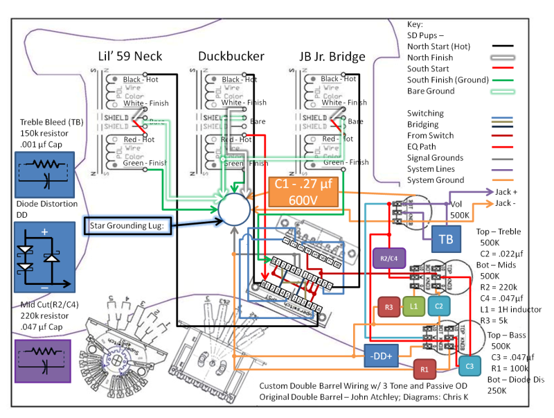 So, my request for help is two fold here, one, are my diagrams correct in their flow and connections, and secondy, are my proposed electronics values withing reason? Thanks for all the help, and I'll definitely post pics of things as they go together. |
|
|
|
Post by sumgai on Apr 13, 2012 2:20:35 GMT -5
bimmy, Oh, so sorry, we just emptied the pool for maintainance! Hope you didn't hurt yourself!!  In other words, your Bass control isn't.... it's yet another Treble Treble-cut control, with different values. Watch out that your Mid pot doesn't end up doing its magic all in one small segment of the pot's total rotation. I suggest that you have an assortment of pots on hand for experimentation purposes.  HTH sumgai |
|
|
|
Post by newey on Apr 13, 2012 6:08:44 GMT -5
bmic 1980-
Hello and Welcome to G-Nutz2!
The end result of the thread on passive EQ was a suggestion to breadboard the thing to see if it worked in a real-world setting. As far as the passive distortion circuit, I assume you've listened to JohnH's sound clips, to know the limitations of these things?
No time to vet your circuit, off to work at the moment, but the weekend is coming, so more feedback will be coming as well, and soon . . .
|
|
|
|
Post by sbgodofmetal on Apr 15, 2012 10:16:31 GMT -5
Here's a sugestion for the double barrel mod instead of cutting your pickguard and addindding another fiveway selector just remove both tone pots and install two six way rotary knobs in their place. they can be had at radioshack for around $3 a piece leave the 6th position on the first one and the 1st position on the second one open or no load, and that old 5way just put your tone caps ine the old pickup spots and replace your volume pot with a dual concentric double stacked pot and voila! Your guitar will have the functionallity of a standard strat AND the double barrel strat with the added bonus of a varitone all while keeping its stock appearance. I actually have a schematic on here for it somewhere I'll try digging it up after I get out of church unless someone else beats me to it (cough cough... sumgia....cough cough...) good luck
|
|
|
|
Post by sbgodofmetal on Apr 15, 2012 12:23:10 GMT -5
Almost forgot if your wanting passive overdrive just put two low voltage schottky diodes in parallel in the neck position of the five way switch. I will try drawing up a diagram and posting it this evening. Also since your using a mega switch, if I remember correctly on how its wired, you can get at least three different tone caps on it plus the o.d. diodes. And for your treble tone solder both ends to the pole instead of grounding them for a bass cutting effect on that tone selection. I'd recommend a .020uf for the treble an .050uf for the mid, and wire an .050uf and a .039uf in series for your bass.
|
|
bmic1980
Rookie Solder Flinger
Posts: 14
Likes: 0
|
Post by bmic1980 on Apr 15, 2012 22:51:25 GMT -5
bimmy, Oh, so sorry, we just emptied the pool for maintainance! Hope you didn't hurt yourself!! I thought it looked funny before I jumped, no wonder there wasn't a splash... In other words, your Bass control isn't.... it's yet another Treble Treble-cut control, with different values. I drew that portion based on my best guess from what was in the the EQ thread, I wouldn't be a bit surprised if I misinterpreted the spice drawings. The end result of the thread on passive EQ was a suggestion to breadboard the thing to see if it worked in a real-world setting. As far as the passive distortion circuit, I assume you've listened to JohnH's sound clips, to know the limitations of these things? I have listened to the clips with the passive distortion circuit, and I like the particular tone. I agree, probably not for everyone, but it provides just a little bit difference. As far as the EQ, I followed that the thread had come to a point of lets burn some fingers ad see what we come up with, and since I'm starting this rebuild, I don't have to much problem being a guinea pig for it. Here's a sugestion for the double barrel mod instead of cutting your pickguard and addindding another fiveway ... ...Almost forgot if your wanting passive overdrive just put two low voltage schottky diodes in parallel in the neck position of the five way switch. ... And for your treble tone solder both ends to the pole instead of grounding them for a bass cutting effect on that tone selection. I'd recommend a .020uf for the treble an .050uf for the mid, and wire an .050uf and a .039uf in series for your bass. I've already loaded my pickguard, and I wasn't to worried with the difference in the look in the first place, kinda what I was going for. As far as using the Varitone idea, while I like the idea in theory, my preference would be to not have only a single master tone. My preference would be to have a different tones for each pickup, or the possible EQ. That, and its where I'm at with parts already, and if I buy anymore the wife might start getting mad at me. Definitely interested in your ideas with the tone pots and capacitor values and the like. Thanks again everyone for the assistance. |
|
bmic1980
Rookie Solder Flinger
Posts: 14
Likes: 0
|
Post by bmic1980 on Apr 20, 2012 17:40:19 GMT -5
Did I make a mis-step somewhere inadvertently in forum etiquette?
Anyways...
What adjustments can I make to the passive EQ so that it functions in the right direction, even if not in the right frequency bands, I don't mind being a guinea pig for it. I'm only wedded to the pot values as they are what I have already, but I would assume in theory I could modify those well enough with static resistors (I assume in theory I could be wrong as well). Like I previously mentioned I drew the schematic based on my best impression as the final point before testing in the original thread.
sbgodofmetal, I reread through your post about cap values, but I'm not sure what you mean by tying both points to the pot rather than going to ground. I assume you mean both ends of the cap attached to the low side of the pot, with a separate ground coming from the same point, essentially putting the cap in Parallel (someone correct me if I wrong) to the ground rather than in series?
The only parts I've yet to purchase for this project are the fine electronics (caps, resistors, diodes) I already have all my switches and pots. I may wire the volume and EQ module into a small box and use it externally on my ovation knockoff as a test bed while I work on refinishing the body of the strat, which would be beneficial as it eliminates the switching portion with only one pickup. once again, any and all feedback is greatly appreciated.
|
|
|
|
Post by newey on Apr 20, 2012 20:27:50 GMT -5
No breaches of etiquette, bmic! I don't know why no one has responded to your questions yet . . .
What I have been able to trace on your diagram looks OK, but I'd like to have another set of eyes look at it before you start wiring. I'll try to give it a more thorough look over the weekend.
As far as values, the last ones I mentioned were only a starting point. I was going to continue my 5spice sims with RT's suggested values, but haven't gotten back to that as yet. We left it that further real world experimenting was needed.
This can be done external to the guitar to zero in on the values, as you suggest. I wouldn't build a box to start off, just breadboard it to see what you get.
|
|
bmic1980
Rookie Solder Flinger
Posts: 14
Likes: 0
|
Post by bmic1980 on Apr 20, 2012 22:18:24 GMT -5
This can be done external to the guitar to zero in on the values, as you suggest. I wouldn't build a box to start off, just breadboard it to see what you get. A box in my case here was going to be a small cardboardbox with holes for the pots... but anyways. To show my N00bness, I'm not really sure on how to go about bread boarding it, but I think I can wing it in the cover of a shoe box with just the pots so that I can get to the caps and resistors. Thanks for the follow up. I suppose my only question would be, how would the wiring be different if the EQ is behind the volume (as it would be outside the guitar)? |
|
|
|
Post by newey on Apr 20, 2012 22:37:18 GMT -5
You can get a simple breadboarding kit at Radio Shack, or you can make one yourself. They look like this and cost under $10 USD. This allows you to lay out your circuit and easily swap components in/out. You just stick stripped wires ends into the holes as needed, no soldering required. ![]() rsk.imageg.net/graphics/product_images/pRS1C-3721764w345.jpg rsk.imageg.net/graphics/product_images/pRS1C-3721764w345.jpg [/img] You can also buy a kit of pre-stripped jumper wires of various lengths, which saves the tedium of stripping dozens of jumper wires to use for the circuits. |
|
|
|
Post by sumgai on Apr 21, 2012 4:36:55 GMT -5
bimmy, Sorry for the non-participation, but sometimes I have short periods of lucidity (where I'm no longer Nutz), and seemingly just vanish. Don't worry, it's not catching or anything..... I hope!  Let me think on this for a few minutes, I should be back shortly..... |
|
|
|
Post by reTrEaD on Apr 21, 2012 15:29:53 GMT -5
What adjustments can I make to the passive EQ so that it functions in the right direction, even if not in the right frequency bands, I don't mind being a guinea pig for it. I'm only wedded to the pot values as they are what I have already, but I would assume in theory I could modify those well enough with static resistors (I assume in theory I could be wrong as well). Like I previously mentioned I drew the schematic based on my best impression as the final point before testing in the original thread. I'd change the configuration of the bass-cut circuit. Think treble-bypass on a volume control, but limiting the amount of volume cut. I'd also locate it after the mid-cut, so they won't interact. I also think the value of the cap for the bass cut needs to be smaller.   I suppose my only question would be, how would the wiring be different if the EQ is behind the volume (as it would be outside the guitar)? You could build it outside the guitar for testing, but don't turn the guitar volume down. Else this will add resistance in series, before the tone-cut networks. This make them much more effective when the volume is rolled down a bit and less effective when the volume is at max. |
|
bmic1980
Rookie Solder Flinger
Posts: 14
Likes: 0
|
Post by bmic1980 on Jun 8, 2012 1:34:13 GMT -5
Sorry for the delay in reply here, life has been bus over the last few weeks. I'm finally getting back on this project, have most of my parts, minus my caps and resistors, thought I would ask for some QC from the wire masters here. I have my order set up through mouser, with my project here: www.mouser.com/ProjectManager/ProjectDetail.aspx?AccessID=363ab406ac Currently, I'm working off of the values as suggested by retread, and those are what I have ordered. The only thing I haven't been able to figure out for my order is the inductor. Any suggestions on what to order through mouser would be greatly appreciated. Any other suggestions are appreciated as well. One other question in regards to the the concentric pots, I'm assuming the bottom pot is the top knob, is that correct? I should be getting a new thread up in the appropriate forum in regards to the overall build, I'll post a link in here once I have it up. Thanks again for all your help. |
|
|
|
Post by newey on Jun 8, 2012 5:28:21 GMT -5
Back in September 2008, we had a discussion in a thread about The Q filter. Our late guru ChrisK pointed out: The Q filter thread goes on to discuss switching inductors in/out, or using both halves of a transformer selected by a switch. Unfortunately, when I copied the quote to notepad, I lost the link coding for the Mouser link, so I'll go back and nab that for you as well. EDIT: Here's the Mouser link |
|
bmic1980
Rookie Solder Flinger
Posts: 14
Likes: 0
|
Post by bmic1980 on Jun 8, 2012 11:38:47 GMT -5
Newey, Thanks for the reply, I'll have to read through the Q thread a little more to see if it'll all make sense to me. I had also found these looking through mouser: www.mouser.com/Passive-Components/Inductors/_/N-5gb4?P=1z0wjb0Are these more specifically what I'm looking for? I ask due to their slightly smaller size (with the one exception) and smaller price. Thanks again for the assistance, and hopefully either by the end of the month, or sometime in August, I'll have completed pics and sound files to post up. |
|
|
|
Post by newey on Jun 8, 2012 20:59:57 GMT -5
Not sure on that, bmic, let's let someone else weigh in. I don't know why a power inductor wouldn't work, but I'm not sure on it.
|
|
|
|
Post by reTrEaD on Jun 8, 2012 22:44:44 GMT -5
The Triad unit is way big. Doubt it would fit in a guitar. The other two are the wrong value. 1000uH = 1mH. You need 1H.
|
|
|
|
Post by sbgodofmetal on Jun 9, 2012 1:19:46 GMT -5
sbgodofmetal, I reread through your post about cap values, but I'm not sure what you mean by tying both points to the pot rather than going to ground. I assume you mean both ends of the cap attached to the low side of the pot, with a separate ground coming from the same point, essentially putting the cap in Parallel (someone correct me if I wrong) to the ground rather than in series? On the caps I believe your refering to the .020uf cap both ends get soldered to the lugs instead of one to lug and one to ground. Its a bass cut basically allowing more high frequencies to get through. If its the wiring of .050uf and .039 together in series solder one end of each to the same lug and the others to ground. Basically its two caps on one lug for a total capacitance value of .089uf. As far as the double barrel mod you said you already had the guard cut and both switchs mounted so I'm gonna post this as a referance in case you'd like to give it a try with another project.  I used two 5ways in this diagram with a push/pull to toggle one of them on or off. Its better in my opinion to use two 6ways with pos 6 left no load on the 1st switch and pos 1 on the 2nd switch. I accidentally drawn all my caps ungrounded that wasn't intentional for all of them, I meant to only draw the .022uf that way and the other two are grounded. |
|
|
|
Post by reTrEaD on Jun 9, 2012 14:05:59 GMT -5
I'd suggest he not try it. Ever. It seems your "double barrel" has a dud in the second chamber. Only the left side of the first rotary and the 2 and 4 positions of the right side the first rotary accomplish anything. The rest of the right side of the first and all of the second rotary are like a dog chasing its own tail. It can't do anything more than make redundant connections to what was already made by the first rotary switch. Pointless. Also pointless is the left side of the push-pull. Since both the upper throw connects the first rotary switch to the CCW lug of the volume control and the lower throw connects the first rotary switch to the CCW lug of the volume control, there is no need for a switch. Just make that connection directly. I'm puzzled by the fact that you connect the signal to the CCW lug of the volume pot. This would mean the volume control would work in the opposite direction (full volume at CCW no volume at CW). I strongly urge you to actually build and test a circuit before recommending it on this forum. Also acceptable would be to have it vetted by other members, in lieu of an actual build. But consider this one DOA. There's far too much wrong with it to even use it as a starting point. |
|
|
|
Post by sbgodofmetal on Jun 9, 2012 18:10:18 GMT -5
Rt comment noted and thanks for the more politly way of putting it this time. As far as actually testing it I'm putting it in a strat type design I'm currently working on but fisrt I've some $600. Dollars worth of bills to pay within two weeks and my sons 4th birthday on the 18th so after that ill be getting the first set of parts to work into this project so testing and trouble shooting will take place then and a revised diagram will be given with all nessasary corrections made. I'll keep you updated on my progress as I go through it. More will be posted about it in my project one goin strat crazy thread later. But just for the sake of knoledge itself were did I go wrong on the switching exactly? These are just dp6t rotaries so will I be fine with just two poles on each switch? or should I go with more?
|
|
bmic1980
Rookie Solder Flinger
Posts: 14
Likes: 0
|
Post by bmic1980 on Jun 9, 2012 19:33:52 GMT -5
Retread:
I figured he Triad unit was two big, and the other two were what came up when you set the filter to 1H. Oh well, looks like I'll use the transformer idea that Newey posted.
SB:
Thanks for the update on the bass cut, I may look into that more as I experiment. I'll stay away from the rotaries myself, but more of an aesthetic reason than anything else, I kinda like the idea of having it look different than stock.
Everyone:
Thanks again for the assistance, I finally got a good coat from my paint's base coat down, so hopefully I'll get another thread over in the lutherie side posted soon.
|
|
|
|
Post by reTrEaD on Jun 9, 2012 19:58:23 GMT -5
and the other two were what came up when you set the filter to 1H. Yeah, I kinda suspected it was a problem with the filter rather than your own math. Keep us posted on your progress. This seems like an interesting project. And if there's anything more we can do to help, don't hesitate to ask. Cheers! |
|
|
|
Post by 4real on Jun 9, 2012 20:01:10 GMT -5
I'm glad you have not given up on your plans sbgodofmetal, but as you can see from most projects here, mine in particular that have gone on for many pages and required many revisions and corrections and explanations of the intended goals...this is the way to do it. 1. Start ones own thread on a particular aspect, say wiring plan 2. State the goals and other aspects desired clearly this will generally result in links to similar things here or have been done to guide in that process 3. Draw out the component 'modules' that clearly and post them so they can be vetted by more experienced members who are keen to help 4. If there are things that you are unsure of or require a second opinion, ask for sure but don't assume 5. Build the prospective design outside the guitar, preferably on cardboard template that can be tested while the guitar is in a playable condition... here is the tricky 22 dual in my LP...I will typically do and recommend this on any guitar. Purely because of this it worked first time and neat enough to troubleshoot before installing into the guitar. Wires like pickup wires and such to do this kind of thing from under a scratch-plate can always be shortened later when you know it works. Don't let enthusiasm, which is of course a great thing (and all of us have tended towards some complex and idiosyncratic ideas, it is after all the reason for this thread) get the better of you. It is a factor of any site like this that has a good reputation and wants to keep it that anything that is proposed be actually built and working, all the 'experts' even through the above process can and do get it wrong. You will find that this is true of forums that show circuits that such things are clearly not 'ok' unless verified...verification requires not just a drawing but a successful build. Your own thread is an important one for such things. It is also a good idea that you work on one part of a project at a time and work through the obstacles one at a time, it can mean that a thread gets a little long...take for instance my last one which was a complex and ambitious project. guitarnuts2.proboards.com/index.cgi?board=wiring&action=display&thread=5970This took quite some time, but I broke it up into several sections, there was the building and construction side so that I could get it to a working instrument. The attempt to build a tuning system and the consideration of options and direction changes to better the results. Then the wiring that needed considerable help to integrate the piezo and mag side and the stereo functions and such. buffers and such...still not entirely happy with this...and yet there is still the idea of a 'hex' system that has not really started yet but prepared for. Over confidence and assumptions are the enemy of success, plus being open and adapting others ideas into your own often result in even better results. Going full steam though, from my own experience can often result in an expensive mess of wires that is impossible to troubleshoot. I think it is important to note with most of these kinds of designs, as far as I can see, many of these 'tone control' schemes in passive guitars can only cut frequencies at best...too much may well result with cutting so much out it produces a weak signal and perhaps result far less than anticipated. ... The guitar of this thread though has many features that I like in a guitar and will be cool to see how it all comes together...could be onto a winner here! |
|
|
|
Post by reTrEaD on Jun 9, 2012 20:01:30 GMT -5
Rt comment noted and thanks for the more politly way of putting it this time. Yeah, but what good did it do? It seems tact a tack-hammer is really no substitute when a sledgehammer is called for. As far as actually testing it I'm putting it in a strat type design I'm currently working on but fisrt I've some $600. Dollars worth of bills to pay within two weeks and my sons 4th birthday on the 18th so after that ill be getting the first set of parts to work into this project so testing and trouble shooting will take place then and a revised diagram will be given with all nessasary corrections made. What you plan to do is no substitute for what you should have already done. I couldn't care less what you plan to do with this circuit in the future. Excuses about why you haven't already tested it are meaningless. Please refer to my previous post, before recommending any circuit to any member on this forum: I'd suggest he not try it. Ever. It seems your "double barrel" has a dud in the second chamber. Only the left side of the first rotary and the 2 and 4 positions of the right side the first rotary accomplish anything. The rest of the right side of the first and all of the second rotary are like a dog chasing its own tail. It can't do anything more than make redundant connections to what was already made by the first rotary switch. Pointless.
Also pointless is the left side of the push-pull. Since both the upper throw connects the first rotary switch to the CCW lug of the volume control and the lower throw connects the first rotary switch to the CCW lug of the volume control, there is no need for a switch. Just make that connection directly.
I'm puzzled by the fact that you connect the signal to the CCW lug of the volume pot. This would mean the volume control would work in the opposite direction (full volume at CCW no volume at CW).
I strongly urge you to actually build and test a circuit before recommending it on this forum. Also acceptable would be to have it vetted by other members, in lieu of an actual build. But consider this one DOA. There's far too much wrong with it to even use it as a starting point. I'll keep you updated on my progress as I go through it. More will be posted about it in my project one goin strat crazy thread later. Don't do that in this thread. If you want to post it on your "project one" thread, that's your prerogative. Maybe you can con someone else into teaching you the basics, but it won't be me. And it certainly won't happen here. Further clutter of bmic1980's thread would be a travesty. We're already making enough of a mess, by giving you reading lessons. But just for the sake of knoledge itself were did I go wrong on the switching exactly? These are just dp6t rotaries so will I be fine with just two poles on each switch? or should I go with more? A better question would have been: "Where did you go right?" In case you didn't get it the first time... I'd suggest he not try it. Ever. It seems your "double barrel" has a dud in the second chamber.Only the left side of the first rotary and the 2 and 4 positions of the right side the first rotary accomplish anything. The rest of the right side of the first and all of the second rotary are like a dog chasing its own tail. It can't do anything more than make redundant connections to what was already made by the first rotary switch. Pointless.
Also pointless is the left side of the push-pull. Since both the upper throw connects the first rotary switch to the CCW lug of the volume control and the lower throw connects the first rotary switch to the CCW lug of the volume control, there is no need for a switch. Just make that connection directly.
I'm puzzled by the fact that you connect the signal to the CCW lug of the volume pot. This would mean the volume control would work in the opposite direction (full volume at CCW no volume at CW). I strongly urge you to actually build and test a circuit before recommending it on this forum. Also acceptable would be to have it vetted by other members, in lieu of an actual build. But consider this one DOA. There's far too much wrong with it to even use it as a starting point. Since attention span doesn't seem to be your strong suit, I'll make a summary: 1 - Don't post junk that doesn't work. 2 - Don't make excuses why you haven't tried it yourself. 3 - Don't clutter other people's threads with incessant post-flooding. 4 - Don't think, even for a minute that I would bother to waste my time trying to teach you the basics of switching. 5 - Type less, read more. 6 - When you're done reading, read it again. 7 - Make a concerted effort to understand what you've read. 8 - If you still don't understand it, go back to #6. |
|
bmic1980
Rookie Solder Flinger
Posts: 14
Likes: 0
|
Post by bmic1980 on Jun 12, 2012 13:15:45 GMT -5
Bringing the thread back on track here...
Parts are ordered and should be here tomorrow (6/13). Have to go pick up a bread board kit, and a soldering iron (no I don't have one yet, yes I have soldered before...). once I get the everything wired up, I'll use my Applause cheap acoustic to get some sound samples to test the modules. I'll have a few more questions here and there as I go along.
|
|
|
|
Post by yakkmeister on Jun 12, 2012 18:07:42 GMT -5
Hey bmic1980! Here's my 2c worth - get a good iron. I have done boat loads of soldering before and at some point lost track of my good iron ... began working on my guitars with a 25W unit my housemate owns ... and found I had to continually re-repair anything I had fixed. Went to Jaycar as soon as I had the cash and dropped $100 on a variable, temp-controlled unit (it's good for about 50W max) and have since had no real dramas with soldering. Well, there was a case of Alpha brand pots burning out very easily - happened to my Dano as well as my latest Amplifier project. So yeah - my 2c. Not bad value |
|
bmic1980
Rookie Solder Flinger
Posts: 14
Likes: 0
|
Post by bmic1980 on Jun 16, 2012 12:53:44 GMT -5
ReTread: I'm trying to translate your simple schematic into a wiring diagram before I wire it up. Schematic: Wiring Diagram 1: 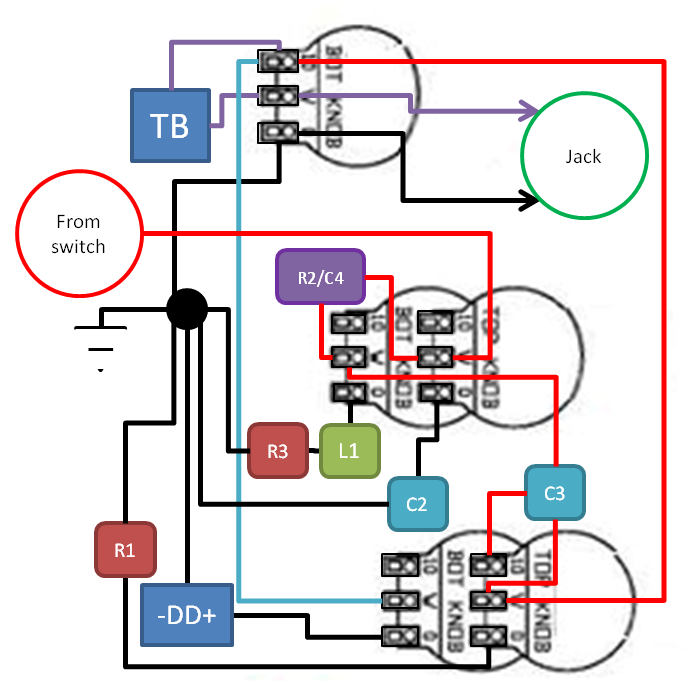 Wiring Diagram 2: 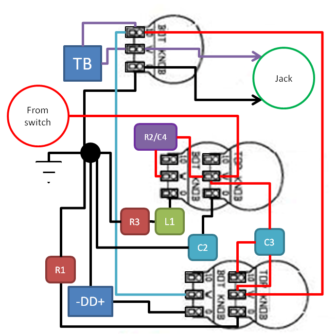 As you can see, I've also added in the diode distortion, which as of now I'm planning to wire more like a traditional tone after the volume. Obviously, any suggestions are welcome otherwise. Also, random question for anyone, which knob drives which pot on a concentric pot? More of an issue on the Bass/Distortion pot as the separate pots have different values. Yak: While spending $100 would be worthwhile if I would be doing a large number of electronics projects, since I'm only doing the one guitar for now, and only have another project guitar for down the road, that expense isn't justified. I picked up a variable (20/40) unit from Radio Shack which should do what I need it to. Thanks for the suggestion though. |
|
|
|
Post by reTrEaD on Jun 16, 2012 14:19:50 GMT -5
Wiring Diagram 1: [image] Wiring Diagram 2: [image] Both drawings look the same to me. What am I missing? Also C3 has 3 wires coming out of it.  As you can see, I've also added in the diode distortion, which as of now I'm planning to wire more like a traditional tone after the volume. Obviously, any suggestions are welcome otherwise. I'm not the person to ask about passive diode distortion in a guitar. It doesn't do much and what it does, doesn't sound pleasing to me. Placing the diodes after the volume control is probably a good idea. When you dial in the amount of distortion you want, you can clean up the sound by rolling back the volume control. So you'll get distortion at the higher volume settings. Look for Schottky diodes with the lowest threshold voltage you can find. Also, random question for anyone, which knob drives which pot on a concentric pot? More of an issue on the Bass/Distortion pot as the separate pots have different values. The inner shaft drives the element farthest from the pickguard. |
|
|
|
Post by sumgai on Jun 16, 2012 18:34:40 GMT -5
rT, C3's upper wire is going to two different places - either the wiper of VR1 or the wiper of VR3
bimmy, The lower diagram is closer to the mark. But look at C3..... The connection between the wiper of V1 and C3 should be going directly to the "upper" terminal of VR3, not through C3. C3 should be across that upper terminal and the wiper of VR3 only. Make that change, and you're good to go. However, let me caution you that the "clipping level" (VR5) is gonna affect the treble booster's action. Essentially, VR5 is gonna act as a load on the t-b circuit, thus changing the timing characteristic of the t-b's capacitor. This means that as you lower the Volume (VR4), you'll get a different tonal response as you rotate VR5. It'll be sort of "what's it gonna do next", until you use it for awhile, then it will become predictable such that you can dial in what you're looking for. Just wanted to caution you, that's all.  HTH sumgai |
|
bmic1980
Rookie Solder Flinger
Posts: 14
Likes: 0
|
Post by bmic1980 on Jun 17, 2012 1:01:51 GMT -5
RT, sumgai pointed out the differences in the diagrams, so no point in me rehashing that. AS far as the diode distortion, it was something to play with and try. I have a total of six schottky's to play with, 3 of the same that JohnH used in his experiment, and 3 others of slightly smaller values. For reference of what I picked up: What John H used (or similar) www.mouser.com/Search/ProductDetail.aspx?R=1N5819TRvirtualkey61370000virtualkey844-1N5819TRand www.mouser.com/Search/ProductDetail.aspx?R=MBR160TRvirtualkey61370000virtualkey844-MBR160TRSumgai: I made the corrections to the diagram as you pointed out. I had to reverse VR2 and VR5 due to the actual pot construction of what I have. 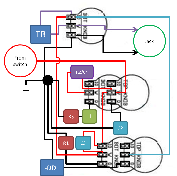 Also, for the issues you pointed out in using VR5, what if I were to put it before the volume? Would the problems still be there, or would there be different problems? For any who can help, I need a little assistance in figuring out how to wire the transformer up as the inductor as Newey (via another thread) suggested. Here's what I picked up: www.mouser.com/Search/ProductDetail.aspx?R=429-7218-RCvirtualkey21980000virtualkey429-7218-RCFor schematic: www.mouser.com/catalog/specsheets/XC-600130.pdfI'm not sure what to wire to. I know I only need to use one side of it (the primary), s in looking at the PDF with the schematic, I'm assuming I would wire it up through pins 6 and 4. Do I have that right, or am I making mistake in my assumption? Oh, and to top off my pain, the pins aren't marked? Any suggestions on how to tell which side is which? |
|