|
|
Post by encikkhalid on Oct 7, 2012 9:30:46 GMT -5
Hi to all member of GN, firstly, I had read the stewmac link and I find it very helpful for a newbie like me. But, I had spend quite sometime but I cannot find any suitable wiring for what i had in mind.
I have 3HB with 4 wires + bare, just some pickup i got from ebay. i want to use the rotary switch 2P6T as pickup selector.
i also wanted to use a varitone switch with the same rotary switch type and also a stacked pot as vol/tone.
on the volume i wanted to put treble bleed mod and on the tone i wanted to put the Black Ice mod.
i have all the parts, just the wiring diagram eludes me.
please help?
thank you very much.
|
|
|
|
Post by pete12345 on Oct 7, 2012 9:57:31 GMT -5
Hi, and welcome to the nuthouse!  Before we can help you much, we need to know what you want the pickup selector to actually do. There are a great number of combinations available from three pickups, but there's only so much you can do with a two-pole switch. For a start, a relatively easy setup would be with parallel combinations of pickups, plus each on their own. So you'd end up with N, N+M, M, N+B, M+B, B as your options. To do anything more complex such as series and/or out of phase wiring you'd most likely need a 3 or 4-pole switch. |
|
|
|
Post by encikkhalid on Oct 7, 2012 18:34:44 GMT -5
Hi, thanks for the reply. I'm not into anything fancy, I figure with varitone, treble bleed mod and black ice, my sounds are quite different already. All in all:
1. N
2. N+M
3. M
4. M+B
5. N+B
6. B
I've got a simple drawing of how my rotary switch look like, but can't figure out how to put it in here.
Thanks.
|
|
|
|
Post by newey on Oct 7, 2012 19:57:51 GMT -5
encikkhalid- Image PostingYou have to host the image somewhere, then use img tagging as explained in the link. While there are various image hosts, Photobucket and Imageshack are the two that we know will work with the Forum software here. |
|
|
|
Post by encikkhalid on Oct 8, 2012 0:13:06 GMT -5
hi newey, thanks for the tips. let's try if i can get this picture uploaded to the forum. really sorry for the crude drawing, i use paint on pc and i'm not artistically inclined, ;D  from the picture, you can see i numbered the 6 ways already. the two rectangular shape is the common pole. a lot of site that i've encountered shows diagram for 4P6T which i'm not into it right now. maybe when my wiring skill is better, i'll be using that switch. right now, i have a stacked pot or dual gang pot as my volume/tone pot and i'm planning to put the treble bleed mod on the volume and the black ice cap on the tone, plus a varitone switch. just an additional pondering, can i put something in there to have some kind of single coil sound? not important enough, but just a wondering question. thanks for any help! |
|
|
|
Post by newey on Oct 8, 2012 6:00:32 GMT -5
You could split one or more of your humbuckers, but you'd need another switch to do so, since you've already designated uses for all 6 positions on your rotary switch.
As far as a diagram goes, the treble bleed and Black Ice are both "modules" that can be incorporated into just about any design. Same thing with the Varitone switch, there are numerous diagrams for that on the web.
The only real "project" is the diagram for your pickup switching. While one of us could draw something up for you, it may be awhile before someone gets around to doing one.
It will be quicker (and you'll learn more in the process) if you try your own hand at a diagram and we'll correct it if needed.
And here's a hint for you. Your 2P6T rotary switch operates like one half of a Superswitch, except yours has one added position which you'll be using to get N + B, and except that yours goes around instead of straight in a line, as with a lever switch.
So, any diagram you find that uses a "half superswitch" can be translated into what you want, just adding the extra position.
|
|
|
|
Post by encikkhalid on Oct 8, 2012 6:49:24 GMT -5
i took your advice and i found two kinds of wiring. but i'm getting confused more than before.  and this one 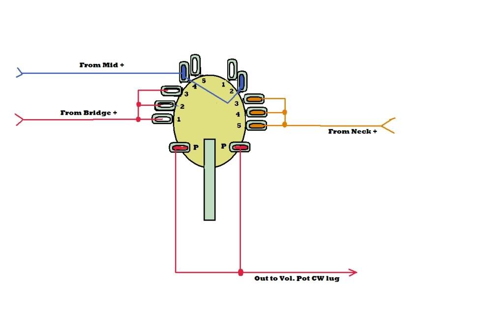 i'll be trying to come up with a diagram of my own in the mean time. thanks again. ;D |
|
|
|
Post by newey on Oct 8, 2012 11:57:59 GMT -5
The first diagram does what you want, except that the N + B is at position #6 instead of at position #5, as you said you wanted. If you don't care too much about where the N + B setting is, you can just use that diagram as the basis for your own. If the position does matter to you, you should be able to translate position #6 to position #5 easily enough.
The second diagram looks suspiciously like one of mine. It has only a 5-position rotary switch, which is configured a little differently than yours. It gives N + B in the 3rd position but omits the middle alone. The first diagram is closer to what you have.
|
|
|
|
Post by encikkhalid on Oct 9, 2012 0:28:51 GMT -5
hi newey, thanks for the reply. i'm sorry if diagram #2 is yours. i just googled for images and posted immediately. i have no intention of copyrighting someone else's work. now, i've been trying to figure it out and i come up with this.  what do you think? and as a note, i'm trying to figure out which wires from my pickup goes where to the position on the switch. is it hot lead to the switch? or some other wires? |
|
|
|
Post by newey on Oct 9, 2012 5:33:47 GMT -5
No worries, it was something I posted here for someone else. It's hardly an original idea anyway.
Your diagram looks fine, and yes, it is the "hot" wires that go to the switch. The "ground" wires of each pickup will be grounded, and the "series junction" wires of each get soldered together.
Of course, before you can know which wires are which, you need to know the color code for the particular brand of pickup you have. If the colors are unknown, some testing will be necessary.
|
|
|
|
Post by encikkhalid on Oct 9, 2012 7:19:22 GMT -5
hi there, thanks for the reply, well, i'd done some tinkereing and testing and here's what i got from my pickups. i'm sorry if it ain't pretty, like i said, i'm not artistically inclined. hehehe.  by following some diagrams and pondering for some times, here's a wiring diagram that i come up with. but it's not complete. as you can see i've got some question marks over some wires.  from diyguitarmods.com post on wiring custom varitone, he said to wire the common lug to the pickup selector pole. but, where should i put it on my switch? i have a 4PDT switch lying around and i hope i could put this also in my guitar to get some kinds of split or phase? or any use to get that single coil sound? thanks. |
|
|
|
Post by newey on Oct 9, 2012 16:35:34 GMT -5
khalid- It may be a day or so before I get the chance to review your diagram. As far as the pickups go, you have successfully determined which wires go to the 2 coils of each one, but that doesn't tell you which two wires get joined together for the "series junction". If you choose wrongly, the two coils will be out-of-phase with each other. So, some further testing will be needed. The Screwdriver Pull-Off TestOf course, easier still is knowing what brand the pickups are. Do you not have any clues on their origin? |
|
|
|
Post by newey on Oct 9, 2012 21:30:14 GMT -5
It goes to the pole (commons) of your selector switch. However, you may find it more convenient to connect it to the CW lug of the volume pot. This is equivalent since that lug of the volume pot is already connected to the switch commons.
Your diagram looks fine, except for the question of wire colors as discussed above. Although you may not know the brand of these pickups, do we know whether they are all the same brand? I mention that because of the odd wire color for the bridge pup (yellow instead of green).
You show the red wires as ground for the N and M pickups, and the yellow as ground for the Bridge pup. If they're all the same brand, my guess would be that the yellow equates to the green wire on the other two pickups. In any event, there's no way to be sure without testing, as described above.
If you are correct about the wire colors, then the green and white wires on the N and M would be connected together to form the "series junction" between the two coils (unless you decide on a coil splitting arrangement, in which case the wires of the series junction will go to the coil split switch).
My guesswork would be different (again, without testing, it's only a guess). If I had to take a blind stab at it, I would treat the greens (and the yellow in the case of the bridge) as being the "hot" wires*, which go to the switch. I'd treat all the black wires as the grounds. And I'd wire the white and red wires of each pickup together for the series junction.
The reason I would make that guess is that the wiring would then track the Seymour Duncan color code. Many pickup brands use the same wire colors as SD since SD is a big manufacturer, and by using the same colors, any diagram drawn for SD pickups can be easily used.
But again, the yellow for the bridge pickup is the oddball, that doesn't follow SD's scheme. That's why I wondered if you knew whether it was the same brand.
*Some bright boy is likely to point out that SD usually shows black as "hot" and green as "not hot". But either way is the same, so long as we're consistent between the pickups (and again, assuming they're the same). I said green to hot because of the oddball yellow wire on the bridge pup, since the odd color usually designates the "hot" wire as for example in RWRP SCs.
EDIT: Also, on the Varitone, note that the standard Gibson Varitone uses a series of capacitors with an inductor; the modified version from the DIYguitarmods website omits the inductor.
He also omits a bypass setting, which he said he didn't find useful. I disagree, I would want the option to have the Varitone off.
You mentioned using a Black Ice™ as well as the Varitone. The Black Ice™ is a type of inductor. I note that you haven't shown the Black Ice™ on the diagram, though. Are you omitting that?
|
|
|
|
Post by newey on Oct 9, 2012 21:44:09 GMT -5
|
|
|
|
Post by encikkhalid on Oct 9, 2012 22:58:08 GMT -5
hi newey, thanks for giving me some explanations on my diagram. the N & M pickups are the same brand, at least that what's the seller on ebay told me, but the bridge pickup is different brand altogether. it came from an old iceman shape guitar that my uncle had cannibalized. mind you that it's not an ibanez guitar. no brand guitar as far as i know. i was trying to save the guitar at that time but not the electronics. i don't know about the pickups. all i can remember is that, my uncle complained of the high screeching noise from the neck pickup before he decided it's best to smash the guitar...  the neck pickup on that guitar is dead after i did some testing but the bridge pickup survived. i did some test also before, but i forgot to mention in the pictures, for the N & M pickups, the green & red is out phase, the black & white is in phase. for the bridge pickup red & yellow is out phase, black and white is in phase. actually, i'm not sure where around the tone pot section of the stacked pot that i have, should i put the black ice.  my stacked pot  *the picture shows 250k but mine is 500k. regarding the varitone, i do understand that i'll be needing an inductor to have proper varitone but i just want to try that option first before i venture any further. so, i have to reduce one capacitor to have the bypass position? is the drawing the same or should i draw another drawing for the 'varitone' switch? |
|
|
|
Post by newey on Oct 9, 2012 23:25:00 GMT -5
Yes, you would drop a cap and bypass the Varitone output past the tone control to the output jack. At least, that's what I envisioned, there are other ways to do it. This version of the Varitone works switching tone pot caps, other versions are separate from the tone control.
I'm not following this. We may be having some language difficulties. You indicated earlier that, for the N and M pickups, Green and red were the wires for one coil, black and white were the other coil. The phrase "the green and red is out of phase" has no meaning: Out of phase with respect to what?
In any event, if you know the bridge pickup is a different type, you'll need to follow the testing protocol to match its phase to the other two pickups, as well as testing for phase between the 2 coils of each pickup. In other words, you now have to test for both intra-pickup phase as well as for inter-pickup phase.
If you guess at it, and guess wrong, worst case scenario is that you'd have to take it all apart again and rewire all three pickups. Given all the connections to the rotary switch, rewiring all 3 will be a chore and will likely make a mess of your switch. So I highly recommend testing this all first to (hopefully) avoid having to rewire it if the pickups end up out of phase.
|
|
|
|
Post by encikkhalid on Oct 10, 2012 4:50:41 GMT -5
Electronics can be so daunting at times...  ok, i checked again slowly with bill jehle's instruction in front of me, for bridge pickup, its like this now: neck side black + white red + yellow bridge side for the neck and middle pickup, it's like this: neck side red + green white + black bridge side how was that? if you're confused, then i'm even more confused... ;D the bridge pickup is a full size humbucker while the neck and middle pickup is rail humbucker. about the varitone, if i didn't solder any caps on the first contact of the switch, will it make a bypass position? i mean, at position 1, the tone is normal, but when switched to position 2-6, then the caps on that contact point will be the varitone, right? oh god, i hope i don't bore anyone from helping me. thanks in advance. |
|
|
|
Post by newey on Oct 10, 2012 6:24:40 GMT -5
No worries. If we get bored around here, we just crank our amps to "11" and jam Deep Purple's "Highway Star" until the neighbors complain . . . ;D
That would work, you'd be taking the tone control out of circuit. This should give a brighter sound since the resistance of the tone circuit is no longer present.
Phase can be a confusing subject. From your readings, I am assuming that, where you show a +, you got a positive reading from the meter when you pulled off? In other words, for the neck and middle, when green was connected to the red probe of your meter, you got a + reading, and likewise with the black?
If that is the case, go back and look at the handwritten diagram that Jehle makes when he does the testing. That shows you how to wire the pickup up.
For the neck and bridge, you would likely chose to make green the "hot" (which goes to your switch) and the white the "ground" (to the back of the pot as shown in your diagram). The red and black get soldered together to make the "series connection" (note that, for the 2 coils of a HB to be in phase with each other, the series junction has to be one "+" and one "-" wire joined together).
For the bridge pickup, the 2 coils will be in phase with each other if you wire the black and yellow together, and wire white to "hot" and red to ground.
But this still doesn't tell us if this wiring will put the bridge in phase with the other two pickups. To be sure of that, we also need to know which coil of the bridge is "North" magnetically and which is "South". We've solved the problem for intra-pickup phase, but not necessarily for inter-pickup phase, since the bridge is a different type.
To check this, you'll need to place one coil of the bridge HB face to face with one coil of either the either the neck or middle pickup. Find which coil of the N or M is wired to the green and red. Place the coil of the bridge with the red/yellow face to face with that coil of the N or M (this can be a bit tricky with the thin coils on a rail, if so, you can also use a magnet with one pole marked for reference).
If we're going to wire green to hot on the N and M, we need to find the Br coil that repels that coil on the rail pups. Remember, "opposites attract", and like coils repel. If the red/yellow coil of the bridge repels the green/red coil of one of the rails, then we would wire the bridge such that yellow goes to the switch, black to ground, and red/white are joined together.
If the two coils above attract each other, then we have to reverse the wiring of the bridge pup so that white goes to the switch, red to ground, and yellow/black get wired together.
|
|
|
|
Post by encikkhalid on Oct 10, 2012 6:45:38 GMT -5
i tested it just now and the red/yellow (screws side) attract the upper part of the rail pickup (red/green). the lower part of the rail pickup (white/black) attracts the white/black (stud side) of the bridge pickup. i'm lost.  EDIT: EDIT:okay, i've been trying to digest everything and i think i can come up up with a new diagram. but i still have some questions. the green from N & M will go to the switch and the white from Br will go to the switch. ok, i got that. the white from N & M and the red from Br go to ground, that is to the back of vol pot, right? the black/yellow from Br are wired together and so does red/black from N & M. to where they are wired to? the bare wires will all go to the same place, the back of the vol pot right? |
|
|
|
Post by newey on Oct 10, 2012 12:28:04 GMT -5
This means that the bridge red/yellow should repel the rail white/black, making those coils the ones that are the same. This is the opposite of our prior assumptions.
As I said:
Note that it doesn't actually matter which is actually the North coil or the South coil, it only matters that we are using the same coil from both the N and M and from the Br. Only the relative polarity matters, not the absolute polarity.
Yes. And using the back of the Vol pot as a ground point is fine. There are other options but that's as good as any.
Yes. If you're using the back of the volume pot as a grounding point, all "grounds" will meet at that point.
These wires form the series connection between the two coils of your HB. They aren't wired to anything else, just to each other- unless you decide to add coil cut options.
It's a good idea to wrap that connection with some electrical tape to avoid it shorting once you button everything up in the cavity. Or, you can use shrink tubing if you're a fan of that method.
By joining the two wires in the "series junction", you've just made your 4-wire HB back into an old-style 2-wire HB. On those old style HBs, the extra two wires were connected internally, meaning that those HBs couldn't be coil split without modifying the pickup (hard to do if the coils have been potted). So, 4-wire HBs were developed to allow for coil splitting. If the coils aren't being split, the extra wires are superfluous and are just soldered together.
|
|
|
|
Post by encikkhalid on Oct 10, 2012 23:11:03 GMT -5
OK, I think I can understand now. But, before I put up a new diagram, what can be used to make the black/yellow wires from Br and red/black from N&M to work as coil cut or is it co tap? I have a 4PDT switch and another 6 way rotary switch.
Which should I use and how should I wire it?
Thank you.
|
|
|
|
Post by newey on Oct 11, 2012 5:54:56 GMT -5
Assuming the 4PDT switch is a two-position switch, either On-Off or On-On, it can be used to cut all three HBs to SC simultaneously (or cut only two, or only one, your choice). To be able to cut coils individually, you'd need more switching.
The rotary could be used to cut each HB individually to SC, and you'd still have 3 positions left over, which could be arranged to cut two HBs at once or all 3 at once, so you could have:
1) N SC
2) M SC
3) Br SC
4) N SC + Br SC
5) Br SC + M SC
6) Br SC + M SC + N SC
Or, #6 could be N SC + M SC if you don't want all 3 at once.
Now, that rotary scheme will make things a lot more complicated, so if you favor simplicity, the 4PDT option is probably the way to go. This would be wired to cut all three coils at once, but would work in conjunction with your rotary setting, so that for example, if the rotary is set to bridge only, you'd get Br SC, etc.
If you want to be able to have one pickup be a full HB, together with another pickup as a SC, then the rotary gives you those options.
Another point to make: Remember our recent discussion about wire colors? We'll need to revisit that if you want coil cut options, because we will then have to figure out which coils we want to cut from each pickup so as to maximize hum-cancelling when in coil-cut mode.
"Coil cut" or "coil shunt" (or "short") are all terms used for this. You'll see people talk of "coil tapping", but that's technically incorrect. We're talking about cutting, or shunting, one coil from a two-coil HB so it operates as a SC. A "coil tap" is a wire that comes off of the middle of the windings of a SC pup, which allows only half of the windings (or some other fraction) of that coil to be used. Some vintage pickups did use actual coil taps, so it's confusing to use that term here.
EDIT: Sorry, I missed your diagram, I didn't page down far enough on my phone this morning. Your tech's diagram won't work, because he's using both poles of the rotary- the two wires from each pickup won't be connected together except when the coil is selected to be cut, so you won't have HBs at all.
To do this with the rotary, you would wire the two wires together, just as we said earlier, then wire that series junction to one lug of the rotary, so that the neck junction goes to lug one, the mid to lug two, bridge to lug three. The common lug gets grounded. You will (so far) be using only one-half of the rotary switch.
This is just the basics, to get the first three positions wired. We need to know what you want to do for the rest, as discussed above, and we'll probably need to use the other half of the rotary to finish this off, again, depending on what you want.
As I said (and as your diagram shows) this 3-rotary scheme is going to get very complicated, and you're going to have a rat's nest of wires to stuff into your cavity. Yu should do some test-fitting of components to be sure you can get everything in there, with leaving sufficient room to be able to wire the 3 rotaries.
Using the 4PDT is more basic, but is much more simple, while still giving you several SC options.
|
|
|
|
Post by encikkhalid on Oct 11, 2012 6:52:37 GMT -5
thank you for telling me it can't be done with a rotary. i was having a headache looking at all the wires drawn across each other. this is my 4pdt switch. it's an on/off/on type.  ahhh... heck it... i'll just do the wiring as per original of our discussion, that is the two wires left from each pickup are connected together and insulated just like that. maybe after i uderstand electronics better, i'll pry it open again (soon i hope... hehe.. ;D) |
|
|
|
Post by newey on Oct 11, 2012 13:58:25 GMT -5
I didn't say it couldn't be done with a rotary, just that the diagram you had was wrong. I did say that I thought it was a lot more simple with the toggle switch.
But if you want to omit the coil cuts for now, that's fine. Your prior diagram looked OK to me, but you probably should redraw it with the appropriate wire colors and let's double check before you start wiring it up.
|
|
|
|
Post by encikkhalid on Oct 11, 2012 16:57:56 GMT -5
Thanks newey for your help for a noob like me. I'll redraw everything with proper color codes and I'll put it up here soon.
Thanks again! ;D)
|
|
|
|
Post by encikkhalid on Oct 19, 2012 8:50:39 GMT -5
hi there, apologees for the silence period. something's come up and i had to attend a course for my current job. (I'm a teacher  anyway, here's the new diagram with colours for the wires.  For a few days i kept thinking whether i want the single coil sound or not and finally i come up with the answer, yes, i do need single coil sound. so, with the 4PDT switch, how can i achieve this? it's ON-OFF-ON type. i did put up the picture of the switch in 2 or 3 post back. some explanation on the black ice, i found the diagram on instructables and since i had these schottkey diode lying around (i never knew they were schotkey's ;D) i thought, why not put 4 diodes to give a bit more crunchier sound? and also, the author did indicates to let one of the point unattached to get that even bit more dirtier sound. so, i thought, why not? thanks for any help for a noob like me. thanks especially to newey for helping me also. |
|
|
|
Post by newey on Oct 19, 2012 14:44:02 GMT -5
encikkhalid-
At work now, so I can't vet your diagram fully at the present, I'll look at it more closely this evening.
But one thing I will mention is that you are now showing the use of a star grounding scheme, but you show the outjack sleeve grounded to the back of the volume pot. If you're star-grounding, all the grounds need to go to that point, including the output jack.
If the guitar's cavity is shielded (and the underside of the pickguard as well), then you can count on the shielding to ground the shells of the pots. If not, you should probably run a ground line from the vol pot to the star ground as well. It may not be strictly needed to do so, but an ungrounded pot shell could theoretically contribute to noise.
|
|
|
|
Post by newey on Oct 20, 2012 22:24:41 GMT -5
OK, I think your diagram checks out, although I'm not sure on the wiring of the Black Ice module without consulting their directions. You don't really need a 4 Pole On-Off-On switch to do coil cuts, it's a bit of overkill and a bit redundant as well. A DPDT On-Off (or On-On) two-position switch would take up less real estate under your pickguard. But here's how you can use the 4P On-Off-On, if you wish to do so. We can use the extra position to maximize hum-cancelling a bit. In this scheme, all of your "series junctions", the two middle wires of your HBs that were just connected together, now get connected to the 4P switch. With the switch lever in the center "Off" position, no coils are shunted and you have all three pickups as full HBs, as selected by your rotary switch. With the lever in the "up" position (which connects the middle lugs to the lower lugs), all three pickups are split to a SC, but the mid pup splits to the opposite coil from the bridge and neck (Like a N-S-N orientation). In this position, both the N + M and the M + B single-coil combinations will be hum cancelling, but B + N will not. With the lever in the "down" position, B + N hum-cancels along with N + M, but M + B does not. This way maximizes hum-cancelling. 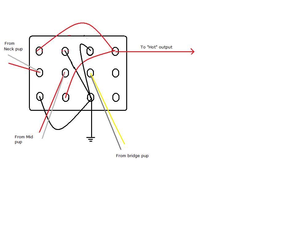 |
|
|
|
Post by encikkhalid on Oct 21, 2012 8:46:18 GMT -5
hi there newey, thanks for your help. i did realized that i could use a DPDT switch, but i just want to use what switch available with me. as this is my first major wiring exercise, i'm hoping to avoid buying new parts, instead utilising what i have on hand.
regarding to the diagram, it's just perfect. now i would be able to play some sounds with the single coil sound.
i'll redraw the diagram properly including the 4pdt diagram that you had drawn for me. i can't thank you enough for that.
|
|
|
|
Post by newey on Oct 21, 2012 9:09:12 GMT -5
A couple of other notes:
First, I note that my wire colors for the coil cut switch don't track yours, I should have paged back to our earlier discussion about wire colors. I couldn't tell the black from the white on your diagram and mixed them up.
But I think you will get the idea, it's the two wires that are wired together that go to the switch for each pickup.
Second, on your diagram, you show position 1 of the "varitone" without a cap, but connected to the tone control nonetheless. That will work, but it leaves the tone pot connected to the circuit, rheostat style, as a sort-of volume control.
If you have the tone control backed off a bit, and then switch to position 1, your volume control won't function as smoothly as you expect. This may not be a major issue for you, tastes differ.
What I had in mind was just not connecting position 1 at all. This takes the tone control out of the circuit entirely, leaving the volume pot alone. This will result in a brighter tone with slightly higher output at that position.
Actually, when I mentioned a bypass setting, I was thinking of the standard Gibson-style Varitone™ circuit, which has the caps wired directly to ground (well, through an inductor as well, in the Gibby version).
What you have is really more of a variable tone capacitor setup. The rotary simply selects a different tone control cap. Having a bypass is less important, since putting the tone pot at "10" effectively takes the caps out of the circuit.
So, given all that, you can either put in another cap at position 1, giving you one more cap selection, or you can bypass the tone control entirely, as I suggested. Or you can leave it the way you show it now, but again, I'm not sure the results will be to your liking.
|
|


