farren
Apprentice Shielder

Posts: 36
Likes: 0
|
Post by farren on Mar 20, 2013 22:51:58 GMT -5
Hello, Sorry my first post has to be a question asking others to do my work for me, but I'm afraid this is beyond my current abilities. It's my hope that because I've already tracked down the most similar diagram possible that it will only require a few minutes of one of your experts' time to modify it for me  I thought I was happy with my Schaller 5-way 'PRS style' megaswitch, but I've been tempted by some of the other more versatile setups out there. I'm using Dimarzios in an HH configuration with 1 master vol, 1 tone for bridge only, and the common superswitch. What I need is: Neck Series Neck Parallel Neck Series plus Bridge Series Neck Split plus Bridge Split (neck side coils on both w/ hum-cancelling) Bridge Series The similar diagram I found in a thread on this forum. It's this one made by newey: 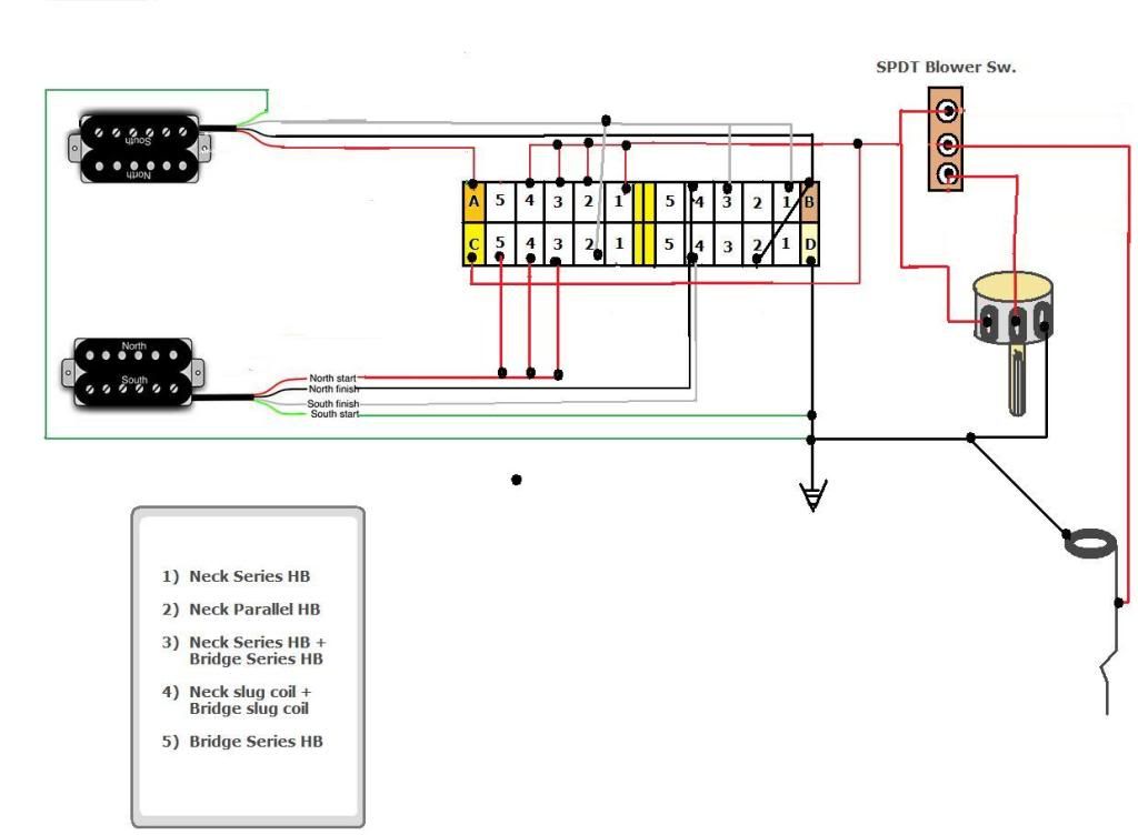 As you can see, it's almost exactly what I need with a few exceptions: I want bridge-only tone, no blower switch, and most significantly, a different neck coil used in position 4. I want to use both neck-side coils as opposed to inner coils. You may think this sounds like a lot of trouble for not much of a difference, but when I tell you I have an Evolution 7 in the bridge position, I think you can understand why I'd want to fatten up the tone just a little with the active coils as close to the neck as possible Here's what I think I know about how to get both neck-side coils going, hopefully without hum/phase issues: I believe bridge is wired in the ordinary way but neck needs to be wired white hot, green/red series link, black ground. That said, I don't know how to pick one coil over the other. Perhaps someone can tell me how to modify the diagram and I can post the revised diagram for the thumbs up (or down), or if it's easier someone could revise it for me? I will be eternally grateful either way  I'm glad to have found a guitar forum that seems to be light on voodoo, mysticism and mythology, and thick on science. My abs are perpetually sore from years of cringing when reading about things like 'singing wood' and other bro-science on other electric guitar forums. |
|
|
|
Post by newey on Mar 20, 2013 23:25:22 GMT -5
Farren-
Hello and Welcome to G-Nutz2!
I'll take a crack at a revised diagram for you, but it may be the weekend before I can get to it.
As far as the blower switch, that can be easily removed. The red output from the SS then goes directly to the CW lug of the vol. pot, while the Vol. pot wiper connects to the output jack hot.
Your bridge tone control can be thought of as a separate module. It will be interposed between the bridge pickup and the SS. You will wire the pot off of the bridge pickup hot, with the wiper connecting the cap to ground.
But, let me take a look at the coil splitting and get a revised diagram up.
|
|
farren
Apprentice Shielder
Posts: 36
Likes: 0
|
Post by farren on Mar 20, 2013 23:52:41 GMT -5
Thanks for the welcome  No hurry as it will be a few days before my retainer clip pliers arrive... I have some dimpled CTS 500 Ks that have a retainer clip around the shaft that I need to remove so I can remove the housing (harder than it sounds...) and file the tracks a bit in order raise them up to ~600 KOhm. That will give me a little more cut with the LiquiFire 7 in the neck, and since the tone control will be bridge-only, I can keep the tone around 90% so as not to brighten up the Evo 7 excessively. |
|
|
|
Post by newey on Mar 21, 2013 21:35:56 GMT -5
OK, farren, before you set into this, let's get a second opinion as to whether I've got this right or not. Here's what I've done so you can follow along: - Added Bridge Tone control
- Eliminated Blower Switch
- Changed position 4 on the SS so as to give the neck screw coil, in parallel with the bridge slug coil.
The only changes are at position 4 on the SS. On Pole "A", the neck slug coil hot is disconnected from the output (red wire eliminated). On Pole "B", the jumper between lug 4 and lug 4 of Pole "D" has been removed (black wire). Lug 1 of Pole "B" is now connected to lug 4 of Pole "C" (added diagonal lavender-colored wire). This should then give you the neck screw coil and the bridge slug coil, which should be hum-cancelling. But, again, let's get a second opinion.  |
|
farren
Apprentice Shielder
Posts: 36
Likes: 0
|
Post by farren on Mar 21, 2013 23:03:28 GMT -5
Thanks! You're the man for doing something for free that some people (*cough* guitarelectronics.com) charge ridiculous amounts of money for. Right now it looks like I will be able to re-wire the guitar on Tuesday so there is plenty of time for others to come along and give the thumps up before then.
In the mean time, I have a bonus inquiry: If I wanted to put a resistor in parallel with the vol pot in certain positions only (most likely just position 2 but I'd like to experiment with position 4 as well) to create a decreased load of somewhere in the neighborhood of 320 KOhm (~600 KOhm pot with 680 KOhm resistor) to filter out a little parallel brightness, where exactly would I place it? It may not prove necessary as the LiquiFire is a pretty fat neck pickup, but I'm still interested to know how to adapt this trick to a super-switch.
If it would require a re-wire of our prospective diagram, forget about it as it isn't worth the trouble of finding another more complicated way of achieving the same modes in each position. I honestly don't think it will even be necessary as neck pickups in parallel don't have half the brightness problems of bridge pickups in parallel.
|
|
farren
Apprentice Shielder
Posts: 36
Likes: 0
|
Post by farren on Mar 22, 2013 1:37:20 GMT -5
Hmm, same thing I said about the resistor in parallel with vol on the neck parallel position applies to this (ie. if it requires dramatic changes and wastes your time forget it), but would it be possible to make the bridge tone a push-pull as well with parallel for bridge on pull? I have an unused CTS push-pull lying around, burning a hole in my pocket, or parts drawer rather It wouldn't have to function correctly when pulled except in bridge series and bridge series + neck series positions. |
|
|
|
Post by newey on Mar 22, 2013 4:27:16 GMT -5
I'll have to look at both the bridge series/parallel, as well as at adding the resistor in Pos. 2. This will be over the weekend now.
|
|
|
|
Post by ashcatlt on Mar 22, 2013 9:13:50 GMT -5
For some reason I can't see the pictures right now, but here's a couple things:
1) Choose the split coils for hum-cancelling and then install the pickups so that those coils are physically where you want them. If the original diagram actually gives you the RWRP coils, but those foils are not closest to the neck, then rotate the pickups.
2) Putting a resistor parallel to the volume pot actual increases the load on the pickup. When we say load, we generally mean current draw. Less resistance = more current demand for a given voltage = greater load. It will reduce treble as you expect.
3) Splitting the coils of a humbucker in series is completely different from splitting them when it's otherwise in parallel. Any S/P switch for the bridge pickup will have to "re-wire" the 5-way also, in order to avoid dead spots. Seems to me like somebody around here figured out how to do it with a DPDT in the not too distant past, but I cant remember who or where.
|
|
farren
Apprentice Shielder
Posts: 36
Likes: 0
|
Post by farren on Mar 22, 2013 11:16:10 GMT -5
Thank you both for the continuing help. 1) Hmm I think it should be possible to rotate either/both both pickup(s) if necessary. I'm not certain because this guitar has an EMG 707 route (think EMG's 4-string bass housing) and my Dimarzios are set in epoxy inside OEM housings. Room might be a little tight but I will see. 2) Ah ok, I just screwed up the jargon there, then. Noted for future reference That is indeed the effect I was hoping for, though again, I'm not sure if it'll be necessary for a pickup like the LiquiFire in the neck, even with a 600 KOhm pot. Any anecdotes involving similar fat neck pickups in parallel would be useful. Right now, my only guitar with a setting that puts both coils of one humbucker in parallel is a guitar with only an Evo2 in the bridge... Hardly analogous. 3) I was afraid of that. Newey: forget I mentioned it. It's really not worth the trouble and honestly I doubt I would use it. I would probably forget I even had a push-pull pot after a while I cleared cache and the pics are still showing up, but just in case, I've uploaded newey's revised diagram externally: i.imgur.com/Tdg8o9F.gif |
|
farren
Apprentice Shielder
Posts: 36
Likes: 0
|
Post by farren on Mar 25, 2013 19:51:58 GMT -5
I think we may still be waiting on a second opinion I've had to push things back at least several days till I can actually implement this wiring, but to re-iterate I'm perfectly happy with the revised diagram above. The push-pull parallel is not important so forget about it. Can someone else confirm it looks to be hum-canceling and with neck-side coils active? |
|
|
|
Post by newey on Mar 25, 2013 22:10:48 GMT -5
Well, back to the original question, I've used all the poles on the switch, and I can't see how to add a resistor to positions 2 and/or 4 without a major reworking of the whole thing. So, I'm glad you're not wanting to pursue that.
However, a separate switch, such as a push/pull, could give a resistor option in all positions of the 5-way, FWIW.
As far as vetting my revised diagram, I can only call out: "Clean up in aisle 3!"
;D ;D
. . . and wait for a response. But I think it's probably OK.
|
|
farren
Apprentice Shielder
Posts: 36
Likes: 0
|
Post by farren on Mar 25, 2013 22:36:28 GMT -5
Hahah thanks man, I'll be sure to let you know how it turns out. Adding a resistor for all positions on pull sounds like a good idea, especially since I decided recently I'll be using a 1M for vol. A cap and resistor in parallel on lugs A and B of vol for treble bleed wouldn't interfere, would they? Is this how I would get the additional resistor on pull? [ ] [ ]
[ ] [A]
[ ] [G]Where A is the resistor that goes to lug A of vol and G is a jumper to ground? That's probably not right, but I figured it's better to take a shot at it than ask yet again "HOW DO I DO THAT" |
|
|
|
Post by newey on Mar 26, 2013 6:17:47 GMT -5
Good thinking! There are various ways of doing the fixed resistor, the one you show is fine and will work. The treble bleed RC filter across the volume pot operates only as you turn the volume down, so it won't "interfere" with the fixed resistor when the volume is at "10". The treble bleed will come into play, together with the fixed resistor, as you turn the volume down, but I wouldn't think of it as "interfering". Your resistor will have already knocked the output of the pickup back a bit, the V pot will knock it back more as you turn the knob down, and the treble bleed will help preserve the higher frequencies as you do so. I used a 1M V pot, together with a 500K tone pot, on a single HB Strat I built a while ago. The HB was a GFS "Dual lipstick tube" type, in the bridge position. My goal was to make it bright, and it is- in spades! I usually play it with the tone backed off to about 7 or so, otherwise it's got that "icepick tone" that sumgai so dislikes. |
|
farren
Apprentice Shielder
Posts: 36
Likes: 0
|
Post by farren on Mar 26, 2013 12:03:39 GMT -5
Ahh great. I like the idea of having that potential on tap in case I need it. I'm just hoping the 1M doesn't make the neck too bright as I'll only have tone on the bridge. I don't think it will be a concern. If it's too bad I can just back off the 6600hz slider on my amp a bit |
|


