|
|
Post by woodstockwizzard on Apr 16, 2015 10:36:56 GMT -5
I've seen a lot of blend pot circuits, but none of them make any sense so I designed my own.......

|
|
|
|
Post by sumgai on Apr 16, 2015 11:48:04 GMT -5
'wizard, I moved your thread, as this is not a fully-realized design, but instead is actually a module that can be incorporated almost anywhere, in other designs... thus it's a module. And not badly done, either.  Thanks for the input, and hope you find it a good idea to stick around.  sumgai Under-Assistant to the Chief Cook & Bottle Washer |
|
|
|
Post by Yogi B on Apr 19, 2015 17:53:32 GMT -5
Since this has piqued my interest, as I too am left feeling less than satisfied with the normal blender pot designs, so I decided to do a SPICE simulation of this design and a comparison to the (mainly) standard dual-gang blender pots whilst I was at it. Also I must too praise your design as it solves the two issues I have with the common blender implementations: which are either that the sweep of the blend is focused too much towards the individual pickups thus, especially with pots that have a centre detent, I find it difficult to get near but not quite equal blends -- or that the circuit sucks too much volume / treble from the output.
As a side note, a hurdle I had to conquer first was figuring out how to implement a SPICE model for centre tapped potentiometers that was easily adaptable to alternate tapers -- I discovered the key was splitting it into two potentiometers one before the centre-tap and one after, switching the wiper at the halfway point.
Anyway here are resulting plots blending from a typical single coil pickup to two in parallel, all the pots were 500kOhm and where appropriate used a true log taper i.e. a smooth exponential curve asymptotic to zero -- not a piecewise approximation. The modelled circuit also included a capacitance of 300pF to ground representing a relatively short 6 foot cable. In the first column you can see I've done a standard AC sweep focusing on the 2kHz - 10kHz range around the resonant peak, and secondly to offer an alternative perspective (admittedly with a different set of limitations) I plotted a transient analysis with an input signal of 4kHz with the blended pickups out of phase with each other, hence why we have zero volts which is the centre position. 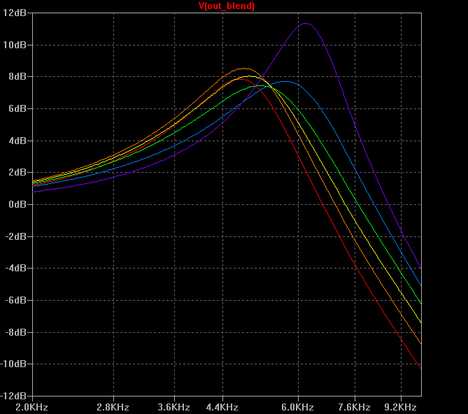 |  | A regular linear tapered blender pot, this isn't terrible but note how quickly we blend away from the both position -- there is a reason why we generally don't use linear pots for volumes. | 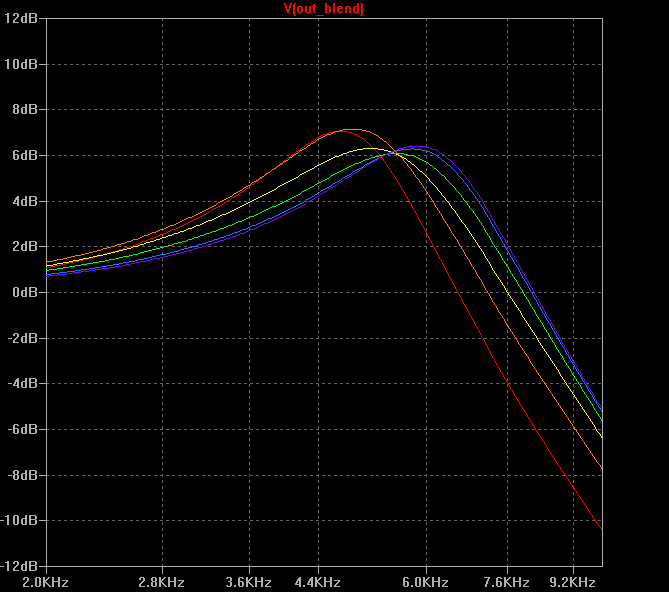 | 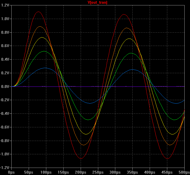 | Also the common log / revlog dual gang pot which gives only part of the combined signal at the centre, but does give a better sweep. | 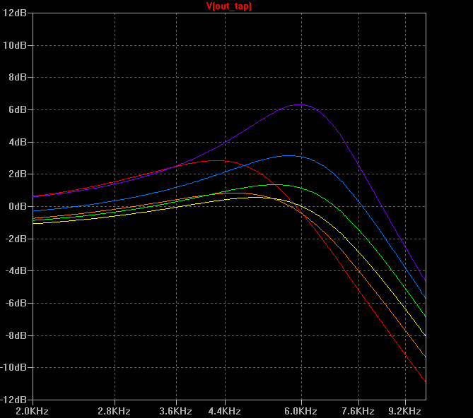 | 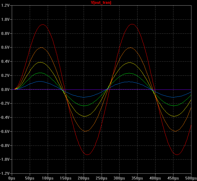 | So this was my first run with WW's new circuit using a linear taper, which provides an even more blend focused sweep, but has quite a poor frequency response mainly due to the fact that we have one half of each of the pots in parallel from the output to ground lowering the impedance down to 125kOhms -- thus I assume this wasn't what you intended... | 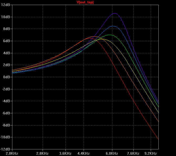 | 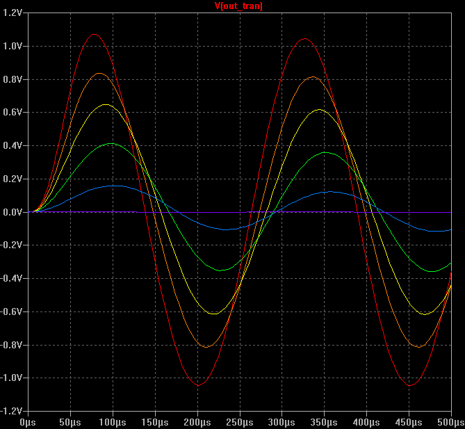 | ... So here's the same thing with a log taper, much better. | 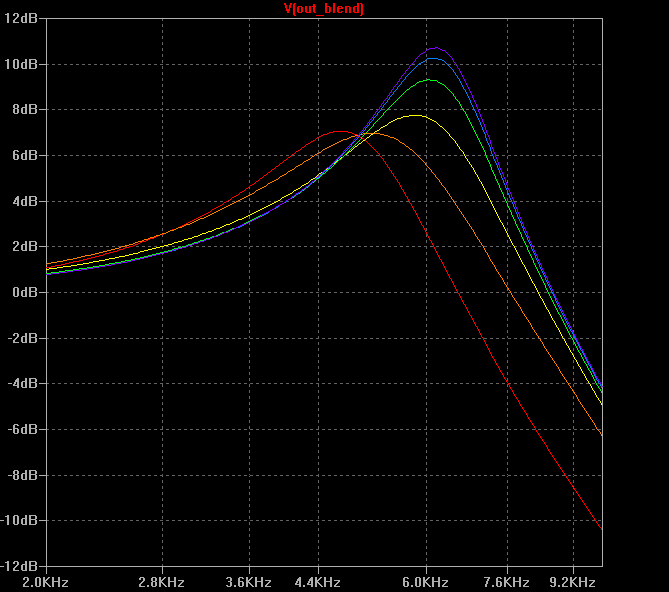 | 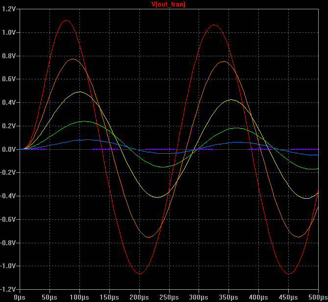 | Finally here's another alternative utilising a 'true' logarithmic blender pot, that combines a conductive trace for half the rotation as with the linear blender and a logarithmic resistive trace for the other half, which when judged to my aforementioned criteria would probably be my pick. Whether this taper is available is another question, although I think I remember seeing such a taper on a spec sheet at some point in the past a quick search for it now has turned up nothing -- but you could always reach for some conductive paint. |
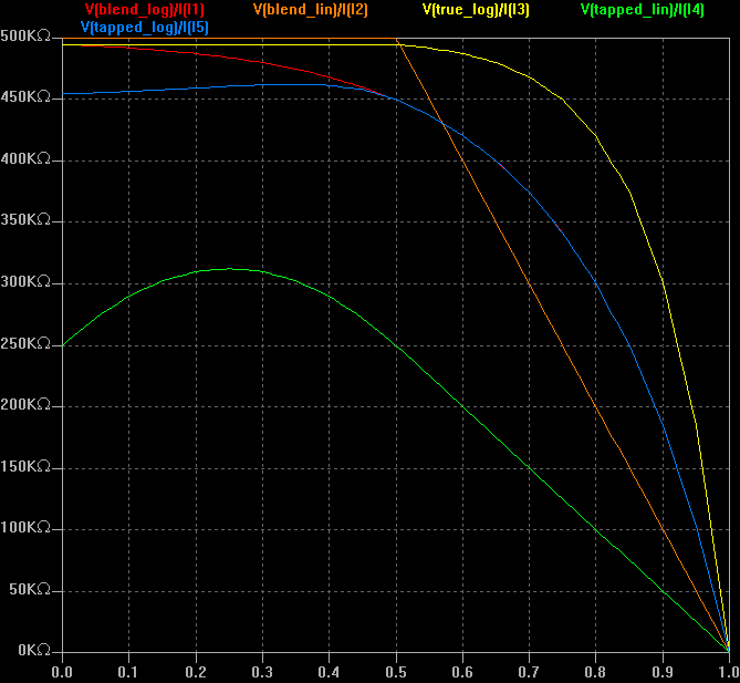
Finally here is a comparison of the resistances between the pickup and the output and between the pickup and ground, respectively: 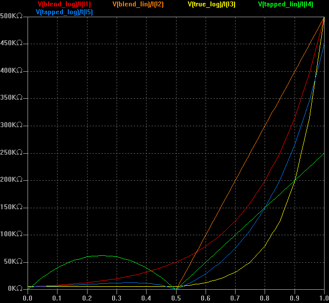
 |
|