|
|
Post by RandomHero on Jan 31, 2006 20:26:57 GMT -5

[glow=red,2,300]!EDIT![/glow] The image posted is the updated version, including Unkl's modifications, and my own mod moving the ground connection from jack negative -> star ground to jack negative -(braided sheild)> volume pot ground.
Tired of my inexperienced hands causing cold solder joints and frying pots, I decided to draw up a diagram of what I intend to be the last wiring mod I do to my H/S/H 7-stringer. So I'm gonna give this diagram to my uncle, who is an electrician by trade and has had more experience using a soldering iron than I've had in breathing, and I know will make a very tidy, professional job of it. This is also my final run because I'll be performing the Quiet the Beast mod on it, as well. So, wiring gurus, please tell me if the above diagram says this: An H/S/H under DiMarzio wiring colors, with a neck-on switch on the volume pot and coil cuts for both 'buckers on the tone, as well as a treble bleed cap a la Telecaster. I am well aware that the leads on the Megaswitch S-model aren't properly attached to the tone circuit, but I'm waiting for a reply from a Stew-Mac tech as to how to properly wire up the lugs from this switch as a tone control for all three pups as opposed to your standard Strat's neck and middle. Also, does anyone see any optimizations that can be made? IE a place where one wire could do the job of two, or otherwise? Thanks all! |
|
|
|
Post by JohnH on Jan 31, 2006 20:55:10 GMT -5
RH - nicely drawn diagram. That ring is the star ground? - it could slip under a pot shaft, and I like that idea because I also hate soldering to pots. Im not familiar with that switch, so cant check that part.
The coils cuts are done by shorting one coil on each Hb. That works and is a common technique. Some folk are concerned that this can cause induced currents that spoil the tone or sustain. My view is that this is not a problem in practice although it occurs in theory. However. the switches can be arranged to avoid this issue without further complication.
My other comment is to do with humcancelling when in coil cut mode. Ideally, you would like one of the coils to be RWRP, probably the middle pup, relative to the coil-cut versions of the Hbs. That may be what you have already worked out, depending on the polarity of your middle pup. You can choose however, with those pups, to have any two of NB, NM and BM single coil combos to be hum cancelling, and then pick which Hb coils to cut accordingly. So if you choose which two are most preferred, the colour positions can be adjusted to suit.
John
|
|
|
|
Post by RandomHero on Jan 31, 2006 21:02:22 GMT -5
My guitar is currently wired as is in the diagram, save for having a cheap stock switch, noisy, uncleanable, ruined pots, and no QTB/star grounding. The standard method of coil cutting I have depicted there has the proper polarities for hum cancellation in 2 and 4. Thanks. =) Yes, that is the star grounding lug, a ring screw in the side of the cavity, soldered to the copper sheild tape. Here's a link for the wiring specs on that switch. www.stewmac.com/shop/Electronics,_pickups/Components:_Switches_and_knobs/3/Megaswitches/Instructions/I-3528.html#details |
|
|
|
Post by UnklMickey on Jan 31, 2006 23:44:52 GMT -5
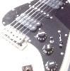
...Here's a link for the wiring specs on that switch. www.stewmac.com/shop/Electronics,_pickups/Components:_Switches_and_knobs/3/Megaswitches/Instructions/I-3528.html#details that link was just way too long to fit. i THINK this is what you're pointing to:  seems like it's functionally the same as a standard Fender strat switch, just different numbers on the lugs? |
|
|
|
Post by RandomHero on Jan 31, 2006 23:46:18 GMT -5
That'd be the case, so that's that. See anything that could be done in a cleaner method with the wiring?
|
|
|
|
Post by UnklMickey on Jan 31, 2006 23:52:04 GMT -5
i'll print it out and disect it.
let ya know tomorrow.
wouldn't hurt if someone else lent some eyes to it too.
different people see these things from different "angles", so the more the merrier when looking for problems, or trying to streamline.
|
|
|
|
Post by RandomHero on Jan 31, 2006 23:53:50 GMT -5
Hence the beauty of this forum.  |
|
|
|
Post by UnklMickey on Feb 1, 2006 3:23:55 GMT -5
 - unnecessary connection to other half of 5-way deleted
- coils not shunted when HBs split
- connection to tone pot made
- i have NOT checked for hum-canceling
since the same coils of the 2 HBs are being used when split, N + B will NOT be hum-canceling i don't know enough about mixing Dimarzio and SC to know if the split you have will cancel with the middle. you won't be able to have all 3 complement each other, so your best course is to pick one pair that won't cancel. then change the "stacking" of one or both HBs so that the other 2 pairings DO cancel. to change the "stacking", connect the green and red, INSTEAD OF white and black. that will change which coil is on "top", and will be active during split mode, but will NOT change the phase of the pup. |
|
|
|
Post by JohnH on Feb 1, 2006 3:52:43 GMT -5
Looks good Unk. Funny how those switch lugs are 1-2-3 in the order middle, neck, bridge, but thats how the Stewmac diagram has them. Do we believe their data? an odd way to build a switch.
Thats a neat coil cut switching arrangement
For humcancelling, looks like RH has already tested that with current wiring, so hopefully OK
J
|
|
|
|
Post by jimplaysguitar on Feb 1, 2006 5:03:02 GMT -5
Lookin good, but I've used some of those enclosed switches in the past, all different. But they've all been 1-2-3, Neck-Middle-Bridge.
Jim
|
|
|
|
Post by jhng on Feb 1, 2006 5:38:07 GMT -5
Looks mostly right to me. I like Unk's modification to the coil split.
BUT I'm also skeptical about those switch positions! I certainly can't see how a standard wafer switch could possibly work in that way. Worth checking the switch with a multimeter to make sure that each position does what it says on the tin.
Hastings
|
|
|
|
Post by RandomHero on Feb 1, 2006 9:43:28 GMT -5
- unnecessary connection to other half of 5-way deleted
- coils not shunted when HBs split
- connection to tone pot made
- i have NOT checked for hum-canceling
since the same coils of the 2 HBs are being used when split, N + B will NOT be hum-canceling i don't know enough about mixing Dimarzio and SC to know if the split you have will cancel with the middle. you won't be able to have all 3 complement each other, so your best course is to pick one pair that won't cancel. then change the "stacking" of one or both HBs so that the other 2 pairings DO cancel. to change the "stacking", connect the green and red, INSTEAD OF white and black. that will change which coil is on "top", and will be active during split mode, but will NOT change the phase of the pup. I just wanna check because it doesn't seem like I understand a couple of the things. Firstly, the connection between 4 and 8 is shown as neccessary on the diagram. I -have- used lever action Megaswitches before, and those are the pole positions; funny huh? It's still the sturdiest, smoothest switch I've ever used. Second, with the wiring on the coil cuts, will that give me humbucking mode with the pot pushed in, and SC with it out? It looks like it but I'm not entirely sure. Also, the wiring configuration I have in my original diagram on the coil cut is the one I currently have in my guitar; does that mean I have hanging coils causing more noise in my current configuration that will be fixed with this mod? I know I'm asking a lot of annoying questions, but bear with me. I have a logn way to go if I'm gonna understand JohnH's post in the Schematics section before I start collecting my retirement.  |
|
|
|
Post by UnklMickey on Feb 1, 2006 11:19:40 GMT -5
this should help when trying to understand how this switch has an unusual arrangement on the connections   EDIT: i've placed the picture of the T model up too. you can see that they're the same picture. so don't try to figure out the switching from the photos. only good to get an idea of how they're constructed. EDIT: i've placed the picture of the T model up too. you can see that they're the same picture. so don't try to figure out the switching from the photos. only good to get an idea of how they're constructed.it seems like it would be much more sturdy than a superswitch, but at the price of versatility. RH, since you won't be using the other half of the switch to feed multiple tone controls, you only need one pole. i didn't check to be sure that lug 4 is the pole that goes with 1,2,&3! please verify this with an ohmmeter. it wouldn't seem likely that they would use 8, but it didn't seem likely that the connection sequence would be middle, neck, bridge, did it! if you are going to use both poles, why not use both sets of throws too? that way if one of the contacts gets noisy, you'll already have a redundant connection on the other side of the switch. might be overkill if the switch is extremely dependable. i guess i would have known that the hum-cancelling was already worked to your satisfaction, if i had bothered to read the other posts. the original drawing had the unused coils shunted when splitting the HBs. not a noise concern like hanging from hot. theoretically shunting will rob a little energy from the string motion by loading it down, causing a slight loss of sustain. and maybe altering the tone slightly. the jury is still out on whether or not the amount is microscopic or small. i just figure, if you have the switch capacity to bypass, then do it! if you don't. and have to shunt, live with it! the coil cut is with the P-P pulled. BTW sorry if the drawing looked a little butchered. i'm not used to drawing with the wires "jumping" at crossings unk |
|
|
|
Post by RandomHero on Feb 1, 2006 11:50:43 GMT -5
Ok, so... help me understand this...
If a coil is shunted, that means that the hot and ground of that coil are both connected to ground, right? Thusly, the whole unused coil's signal is going to ground, whereas the "hot" of the shunted coil is the "ground" of the remaining active coil anyway, and the remaining coil's "hot" is still connected to the output.
Whereas when a coil is bypassed, it is totally removed from the circuit, and any signal it's generating is stopped at the unconnected poles of the switch?
The "doubling up" on the poles intrigues me. It really seems like a way to make the piece into a tank, not only physically, but also electronically, no? Being the perfectionist that I am, however, I have to wonder if that wouldn't add extra length of wire at the cost of a (likely inperceptible) extra hum.
|
|
|
|
Post by UnklMickey on Feb 1, 2006 12:16:53 GMT -5
...If a coil is shunted, that means that the hot and ground of that coil are both connected to ground, right? Thusly, the whole unused coil's signal is going to ground, whereas the "hot" of the shunted coil is the "ground" of the remaining active coil anyway, and the remaining coil's "hot" is still connected to the output..... that's spot-on. ....Whereas when a coil is bypassed, it is totally removed from the circuit, and any signal it's generating is stopped at the unconnected poles of the switch?.... that's real close. when bypassed in the method i've used, the unused coils have their "hot"s connected to ground along with the "cold"s of the coils being used. the "cold"s of the unused coils are hanging free, but the "hot" end of that coil is connected to ground, so it shouldn't be a noise issue. ... Being the perfectionist that I am, however, I have to wonder if that wouldn't add extra length of wire at the cost of a (likely imperceptible) extra hum. spot-on. including the imperceptible part. a least that my theory, and i'm sticking to it! unk |
|
|
|
Post by RandomHero on Feb 1, 2006 12:32:02 GMT -5
when bypassed in the method i've used, the unused coils have their "hot"s connected to ground along with the "cold"s of the coils being used. the "cold"s of the unused coils are hanging free, but the "hot" end of that coil is connected to ground, so it shouldn't be a noise issue. So... let's see here. If leads on my DiMario are so... (which they are...) Red is the start of coil 1. Black is the end of coil 1. White, connected to black, is the end of coil 2, and... Green is the start of coil 2. With my method, White, Black, and Green were all tied to ground. And with yours... only white and black are grounded... leaving the unused coil grounded from the white wire and dangling out to the green... still an antennae but all the noise it catches are thrown straight to ground anyway, and -not- a pickup because it's an incomplete circuit. ...so... The theoretical energy rob is what I don't understand... I know the laws of physics, well enough, to know that the vibrating string will cause the magnet to generate a signal and that exchange will cause the string to slow faster than it would without the pickup in place. Otherwise it would be free energy and our world's fossil fuel crisis would have been solved in the 80s by men in spandex. ;D But isn't the ceramic magnet of the pickup still a magnet, still taking energy, even if the signal that the coils generate doesn't go anywhere electrically speaking? |
|
|
|
Post by UnklMickey on Feb 1, 2006 13:04:15 GMT -5
...The theoretical energy rob is what I don't understand... I know the laws of physics, well enough, to know that the vibrating string will cause the magnet to generate a signal and that exchange will cause the string to slow faster than it would without the pickup in place. Otherwise it would be free energy and our world's fossil fuel crisis would have been solved in the 80s by men in spandex... yeah, ya can't get somethin' fer nuthin'! when you shunt a coil, it's similar to dynamic braking in a motor. the current you're trying to induce has a path to return. that little bit of current generates heat (yeah, it's small, but it's real) that energy came from somewhere. you guessed it - the energy of the string motion. ...But isn't the ceramic magnet of the pickup still a magnet, still taking energy, even if the signal that the coils generate doesn't go anywhere electrically speaking? the static magnetic field of the permanent magnet will have some effect on string, but it's difficult to express exactly how. it's not exactly like adding mass to the string, but some things are similar. it helps almost as much as it hurts, if that makes any sense. if you're have all the elements in place to generate current, but there is a (high resistance), or no path at all, there is (little) or no current. no current = no energy = no load. at least in terms of our "generator. eddy currents in the metal parts of the pickups and other effects, well, i guess we're just kinda stuck with those things. i'm a little weak on understanding magnetic theory anyway. i do the best i can with what i have to work with. unk |
|
|
|
Post by JohnH on Feb 1, 2006 14:39:47 GMT -5
This dynamic braking is a real effect. Spin a free electric motor and there is little resistance, but short out its connections and it feels stiffer to turn - because it is generating energy (as a generator) which comes from you. Some analogue meters have an 'off' setting, where the coil of the movement is shorted out, which damps the motion of the meter making it less susceptable to damage when moved.
I like the idea of doubling up those pole connections, given that the switch has them - I have had some noisey old switches and that mod will make sure it is still works perfectly when your grandson inherits this guitar
J
|
|
|
|
Post by RandomHero on Feb 1, 2006 14:44:59 GMT -5
On the topic of my beloved 7-string lasting for ever, does anyone know if CTS makes P-P pots?
|
|
|
|
Post by UnklMickey on Feb 1, 2006 15:48:25 GMT -5
On the topic of my beloved 7-string lasting for ever, does anyone know if CTS makes P-P pots? the only ones i recall seeing, were only SPDT or maybe SPST. |
|
|
|
Post by ChrisK on Feb 1, 2006 20:21:22 GMT -5
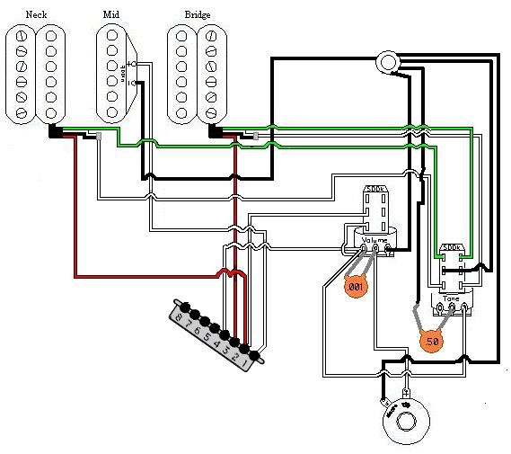
I did these around the time that agriculture was invented, so I don't remember if'n I even checked them. They're a tad churlish in logic, but discernable. The"S" 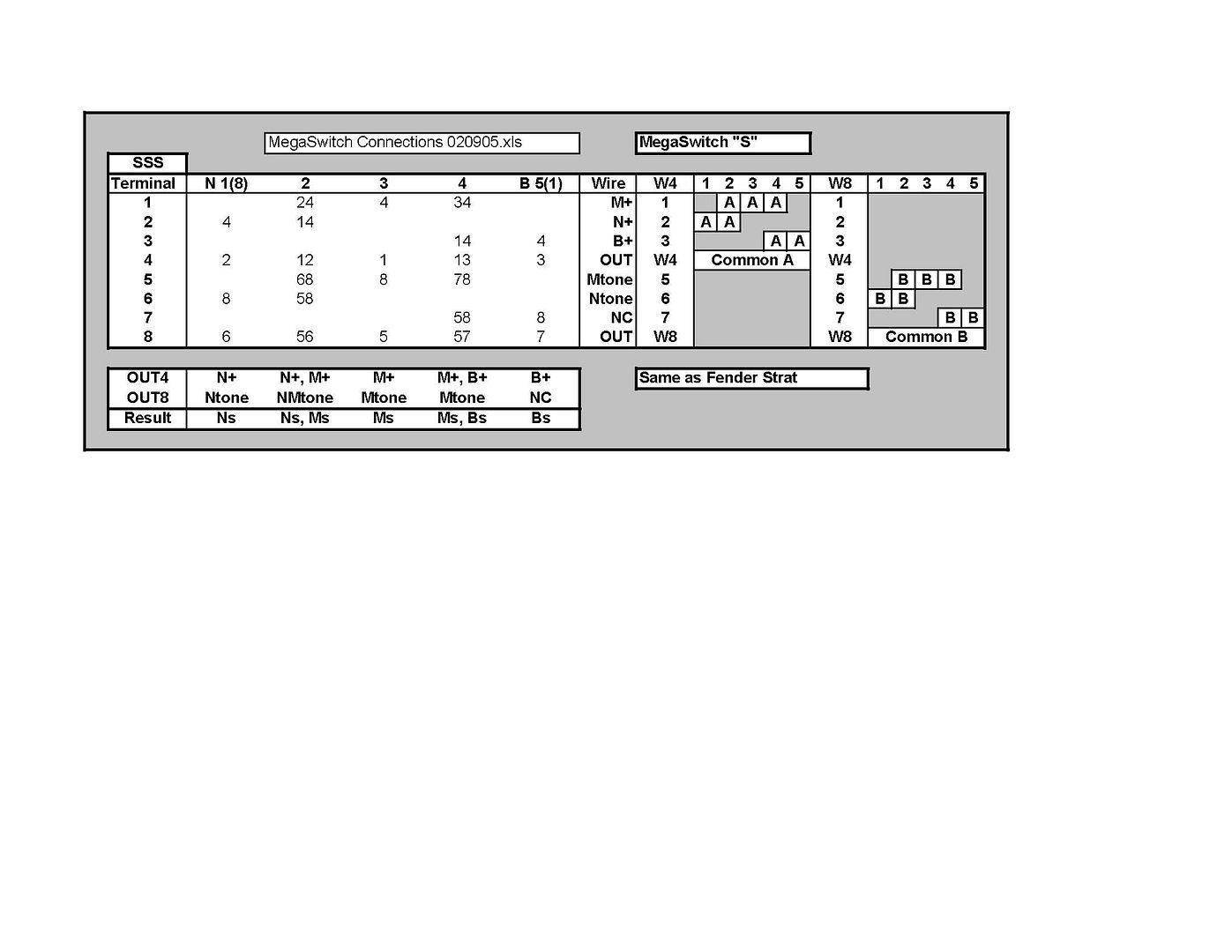 And the "E" 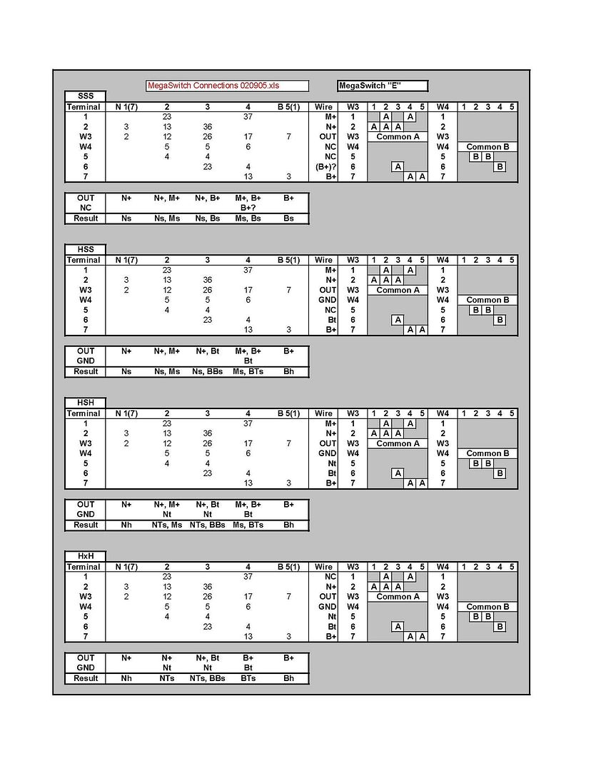 |
|