|
|
Post by ourclarioncall on Dec 15, 2019 18:30:22 GMT -5
Hi folks . I’m trying to figure out if I can get the same 4 pickup selection (1. Neck 2. Bridge 3. Neck and bridge parallel 4. Neck and bridge series) with the following 2 wiring diagrams . Here’s the first one. It has the original source and my hand drawn attempt to recreate it. I’m sure this one works fine , it’s the second one I’m more interested in, as this one has two SPDT switches and the other has two DPDT. I’m wondering if it’s possible to do it with single pole switches then why bother with doubles ? Saying that , the doubles are part of the fender jaguar wiring which may make it more complicated   here is the second one and my attempt at recreating part of the circuit that will give me the four sounds I want just like the first diagram i posted. I got rid of the pots and strangle switch and the other rhythm part of the circuit. I’m sure I’ve probably done something wrong. by the way, my intention is to wire straight to the output jack for both diagrams .No tone or volume pots.   |
|
|
|
Post by thetragichero on Dec 15, 2019 18:36:47 GMT -5
in your dpdt diagram you've got a pole with only one connection on it, so nothing is getting switched
|
|
|
|
Post by ourclarioncall on Dec 15, 2019 18:39:57 GMT -5
in your dpdt diagram you've got a pole with only one connection on it, so nothing is getting switched i think I missed the bit I just added in in purple  best image hosting best image hosting |
|
|
|
Post by newey on Dec 15, 2019 20:38:15 GMT -5
Not sure whether your latest DPDT version will work as intended or not, but it is unnecessarily complex. The first version, using 2 SPDT switches will work fine, but has the potential drawback of leaving the bridge coil "hanging from hot". In your latest 2-DPDT version, the neck instead is left hanging from hot. As we've discussed repeatedly, a hanging coil is not necessarily a deal-breaker, but best practice is to avoid doing so when possible. And it can be avoided by using 2 DPDT swithes- just not in the way you're doing. You will wire the DPDTs just like the SPST switches, and use the extra pole on each to short the hanging coil. Learn all you should know about this topic here- Binary Tree Switching |
|
|
|
Post by ourclarioncall on Dec 15, 2019 21:18:16 GMT -5
Hey thanks for the detailed feedback, very helpful, cheers
I’m not sure what a hanging from hot coil is but I think I can see it in the diagrams although I cant explain it
Does it effect the sound at all or just a bit of an engineers desire for efficiency/integrity
I had a read of the link . Wish I could see those images , I think they would help a lot . Is there no way to repost all of the comments in a fresh thread with recovered images ? Assuming those images can be recovered and someone’s wants to take on the laborious task
|
|
|
|
Post by reTrEaD on Dec 15, 2019 22:42:01 GMT -5
I had a read of the link . Wish I could see those images , I think they would help a lot . Is there no way to repost all of the comments in a fresh thread with recovered images ? Assuming those images can be recovered and someone’s wants to take on the laborious task You can view the images directly if you add an extension to your browser. If you're using Firefox, go here: addons.mozilla.org/en-US/firefox/addon/photobucket-embedded-fix/If you're using Chrome, go here: chrome.google.com/webstore/detail/photobucket-hotlink-fix/kegnjbncdcliihbemealioapbifiaedg?hl=enYou will wire the DPDTs just like the SPST switches, and use the extra pole on each to short the hanging coil. Shorting a hanging coil is not a good solution, imho. Far better to just not connect it to hot at all, when it's not being used. Here's a blast from the past. 2good2beTrue  |
|
|
|
Post by ourclarioncall on Dec 16, 2019 4:12:59 GMT -5
Nice one , il try get the images working
I wish I could understand that schematic, just a wee bit beyond my comprehension 😊 What’s going on in it ?
Cheers
|
|
|
|
Post by newey on Dec 16, 2019 6:08:11 GMT -5
There are 2 DPDT switches, labelled as "SW1" and "SW2". Each switch has 2 poles, labeled "SW1A", "SW1B", etc. Each pole has 3 connections- the middle, or common, connection is a "dot" at the one end of the lever, the round circles that the lever connects to are above and below it. Let's take SW1 as an example: 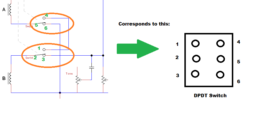 |
|
|
|
Post by newey on Dec 16, 2019 6:28:38 GMT -5
BTW, ourclarioncall, I'm going to get on my soapbox here and use you as an example of one of my pet peeves around this joint. I'm not singling you out, you are far from being alone on this. What I'm talking about is using the "quote button" when replying to a post. There are two ways to quote material from a previous post. There is a "Quote" button at the top of every post. Using this quotes the ENTIRE previous post, forcing subsequent readers to read through the entire previous post, when the reply probably only concerns a small part of the post in question. A better way is to use the yellow Quote button that appears when you reply to a post, in your "reply window". This allows you to highlight a single sentence (or whatever) from the previous post and to quote only the portion to which you are referring. This gets to the point, and avoids scroling through the entire previous post. Simpy highlight the material you wish to quote, then hit the yellow "quote" button, The highlighted material will then appear as a quote in your reply.  The second way is much better, IMHO. |
|
|
|
Post by ourclarioncall on Dec 16, 2019 8:18:47 GMT -5
There are 2 DPDT switches, labelled as "SW1" and "SW2". Each switch has 2 poles, labeled "SW1A", "SW1B", etc. Each pole has 3 connections- the middle, or common, connection is a "dot" at the one end of the lever, the round circles that the lever connects to are above and below it. Let's take SW1 as an example: Hi, hmm, I thought I had it sussed but now I’m more confused 😃 I think you have circled both switch one and switch two , was that a mistake ? I’m thinking you meant to circle switch one A at the bottom of the diagram and switch one B at the top of the diagram . Switch one A would be 123 and switch one B would be 456 ? |
|
|
|
Post by ourclarioncall on Dec 16, 2019 8:22:50 GMT -5
Newey, apologies, I am aware I am guilty of this. I’m on my phone 100% of the time and Its hard work trying to navigate the site. Have to change back and forth to desktop version etc. I found the quoting thing a bit confusing , but il have another look at it to try and keep things tidy
|
|
|
|
Post by ourclarioncall on Dec 16, 2019 8:34:11 GMT -5
Also, I was thinking that when Switch 1 A is moved then Switch 1 B will also move at the same time on the diagram ? As this represented the throw of the switch not the pole , although it includes a portion of both poles .
Hope that makes sense
So for example the first throw would include the terminals 2 and 3 of Switch 1 A and terminals 5 and 6 of switch 1 B
then when you throw the switch to the opposite side you get terminal 1 and 2 of Switch 1 A and terminals 4 and 5 of Switch 1 B
|
|
|
|
Post by reTrEaD on Dec 16, 2019 8:46:05 GMT -5
Hi, hmm, I thought I had it sussed but now I’m more confused 😃 I think you have circled both switch one and switch two , was that a mistake ? I’m thinking you meant to circle switch one A at the bottom of the diagram and switch one B at the top of the diagram . Switch one A would be 123 and switch one B would be 456 ? has half of one switch circled and half of the other switch circled. That's a mistake. Both poles of SW2 (which would correspond to the lower switch on your drawing) are connected to Coil A (which would correspond to the Bridge pickup on your drawing. The dashed lines show which poles are mechanically linked. As I look at your second drawing, with the exception of the wire that connects the upper pole of your upper switch to the upper-right throw, it seems to work exactly the same as Unk's schematic. Where did you get this drawing? If you created it yourself, good show! |
|
|
|
Post by ourclarioncall on Dec 16, 2019 10:20:19 GMT -5
Sorry guys, there’s what looks like a line here but it was a slip of the pen  |
|
|
|
Post by ourclarioncall on Dec 16, 2019 10:24:46 GMT -5
reTrEaD said :
“
As I look at your second drawing, with the exception of the wire that connects the upper pole of your upper switch to the upper-right throw, it seems to work exactly the same as Unk's schematic. Where did you get this drawing? If you created it yourself, good show!”
I’d like to say I sussed it out but no, I stole it from the jaguar wiring in the pic above. Just cut off the other bits like tone and volume etc
|
|
|
|
Post by thetragichero on Dec 16, 2019 10:54:11 GMT -5
ain't nothing wrong with 'borrowing' from "prior art"
the majority of the effects pedal industry (and a good portion of the guitar amplifier industry, not including bass amps because newer class d offs more readily accepted there) is variations on a theme of the same 50+ year old designs
no need to reinvent the wheel to feel accomplished. isolating what you want from a proven design is an invaluable skill round these parts ;-)
|
|
|
|
Post by newey on Dec 16, 2019 17:18:07 GMT -5
Good work spotting my error,you are correct, I circled the wrong half of the opposite switch. What I said still holds, though. Here are diagrams of the internal wiring of DPDT switches. In my prior diagram, note how the center lug on each side ("pole") of the switch, (which are numbered 2 and 5 in my prior diagram) are always connected. On the one side, 2 connects to either 1 or 3, and 5 to either 4 or 6. This then corresponds to unk's schematic, with my numbering. Numbers 2 and 5 are shown as if they were connected to 3 and 6 respectively. (We'll call this "down" in the diagram, but depending on the physical switch IRL, it might be with the lever "Up"). Flip the lever to its other side, and 2 and 5 now connect to 1 and 4. Hope that helps.  |
|
|
|
Post by ourclarioncall on Dec 17, 2019 19:47:24 GMT -5
Hope that helps. Yes, thanks mate, makes sense Is there a reason that the diagram takes the two poles of the DPDT switch and separates them ? Could you also see these as being 4 SPDT switches ? |
|
|
|
Post by ourclarioncall on Dec 17, 2019 19:52:38 GMT -5
As I look at your second drawing, with the exception of the wire that connects the upper pole of your upper switch to the upper-right throw, it seems to work exactly the same as Unk's schematic. Where did you get this drawing? If you created it yourself, good show! When you said the wire that connects the upper pole , upper switch , upper right throw , did you mean the one I posted above as a mistake ? I’d like to say I sussed it out but no, I stole it from the jaguar wiring in the pic above. Just cut off the other bits like tone and volume etc |
|
|
|
Post by reTrEaD on Dec 18, 2019 8:44:08 GMT -5
I was referring to the line you later red-arrowed and said was a slip of the pen.
|
|
|
|
Post by ourclarioncall on Dec 18, 2019 8:54:55 GMT -5
I was referring to the line you later red-arrowed and said was a slip of the pen. Ok, thanks What does 2, 2, 2 - 2 , 4 mean on unklmickeys schematic ? |
|
|
|
Post by reTrEaD on Dec 18, 2019 9:02:16 GMT -5
What does 2, 2, 2 - 2 , 4 mean on unklmickeys schematic ? You'd have to ask him. Two pickups, two switches, double pole - double throw, four sounds ... maybe? |
|
|
|
Post by ourclarioncall on Dec 18, 2019 9:17:41 GMT -5
ah, okay, so it’s not some standardised method of communication
Cheers
|
|
|
|
Post by ourclarioncall on Jan 2, 2020 21:08:02 GMT -5
Hi folks , I’m just revisiting this again. I’ve redrawn the version with DPDT switches and fixed the mistake that my slip of the pen made. how is this looking now ? Is the neck coil still hanging from hot as Newey pointed out in a previous version ?  |
|
|
|
Post by newey on Jan 3, 2020 9:05:52 GMT -5
Your diagram is correct and no hanging coils.
|
|
|
|
Post by ourclarioncall on Jan 3, 2020 9:22:43 GMT -5
Your diagram is correct and no hanging coils. Hooray 😀 good news. I didn’t have a clue what hanging from hot meant but now I think I understand. Is it like a monkey hanging one handed from a tree? When the hot side of a pickup that is switched off is connected /has a pathway to the hot side of the output jack? |
|
|
|
Post by ourclarioncall on Jan 3, 2020 9:24:58 GMT -5
This pic helped  |
|
|
|
Post by reTrEaD on Jan 3, 2020 12:19:34 GMT -5
This pic helped I disagree with the author of that pic. The third example is actually my preferred method, of the four examples. Shunting unused coils should be avoided when possible. Coils hanging from should be avoided when possible. 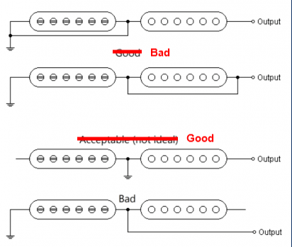 The best method is to have unused coils completely disconnected. However often requires an additional pole. But having an unused coil 'hanging' from ground is not a problem and wouldn't be a problem regardless of the length of the guitar cable. |
|
|
|
Post by newey on Jan 3, 2020 13:58:42 GMT -5
Agree with RT on this one, the best is to disconnect both ends of the unused pickup, but failing that, hanging from ground is fine.
And, as we have said here and elsewhere, having a coil hanging from hot isn't the end of the world. Best practice is not to do so when it can be avoided, but it will probably not be a problem in most electrical environments.
|
|


