|
|
Post by frets on Feb 17, 2021 16:08:41 GMT -5
Hi Guys,
I saw a tone control today where the guy who made it used capacitors to attach the pot to the switch (I.e., Lug 1 to C1 and Lug 3 to C2 respectively).
For example, on the Lug 1 to C1, it has a 150nF cap. And on the first lug of the switch (right above C1), it has another 150nF.
My question is, wouldn’t this just place the caps into series resulting in 75nF on that side?
This was a tone control bought off of EBay that a customer brought in for me to install into his guitar. There’s other stuff on it and I “get “ those, I just don’t get why someone would use capacitors to hook the switch to the pot.😼
|
|
|
|
Post by blademaster2 on Feb 17, 2021 17:58:50 GMT -5
Without a photo or equivalent schematic I am a little lost, but I can possibly see it as a way to save adding a wire, or using capacitors that are on hand to achieve the value that was not in the available parts. Could that be it?
|
|
|
|
Post by newey on Feb 17, 2021 20:52:58 GMT -5
Yes, I am a bit lost, too, not sure what you mean by C1, Lug 1, etc.
|
|
|
|
Post by frets on Feb 18, 2021 16:51:12 GMT -5
Happy Thursday Guys😺😺😺😺 In order to clarify my original post I hope the following will clear it up. So a client brings me the following push-pull tone pot which he purchased off of EBay for $30 USD ($38.61 AUD, £21.47, €24.81). He wants me to put it in his HH guitar. 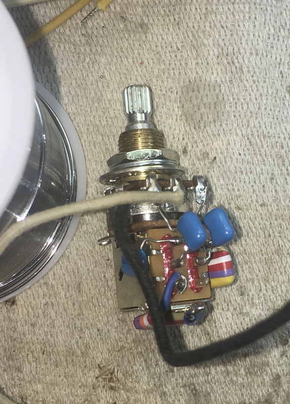 Given I often put a simple 3 cap push pull tone pot in guitars (sorta a 3-way Varitone), I was amused by the complexity of the purchased tone pot and upon review of its features, came to the initial conclusion that the thing is made to look complex in order to make the guitarist think he’s getting something “powerful” in a tonifier. But, my real question relates to one side of the thing. First, please review the following as it will clarify my question that confused. 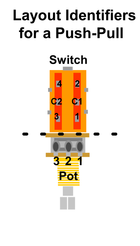 Using the above, the tone pot possesses two 150nF capacitors in the following configuration. 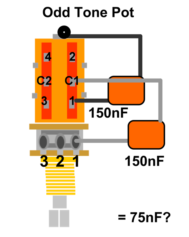 My question is, do the two caps form a series with a resulting value of 75nF? I realize the intent of the 150nF on Lug 1 to C1 is to connect the pot to the switch (in addition to the cap on Lug 3 to C2). But I believe there is a series relationship producing the theorized 75nF. For those interested, the entire layout of this device is: Lug 1 to C1 = 150nF; Switch 1 to Ground = 150nF; Switch 2 = 27nF to 4.7k (obvious Greasebucket circuit); Lug 2 = Hot; Lug 3 to C2 = 47nF; Switch 3 = 4.7nf with a 1M resistor in parallel to ground and Switch 4 is open (Bypass). I prefer building with just a 10nF to ground on Switch Lug 1, a .022 to ground on Switch Lug2; and, a .047 to ground on Switch Lug 3. And connect Lugs 1 and 3 to C1 and C2 respectively. To me, this tone device seems all smoke and whistles. I found it funny but I guess it also irks me that guys would shell out $30 for something they think is “special.” |
|
|
|
Post by newey on Feb 18, 2021 22:04:38 GMT -5
I found it funny but I guess it also irks me that guys would shell out $30 for something they think is “special.” Those engaged in the "Eternal Search for the Lost Tone" often spend much more than that. How many times have you swapped in/out multiple sets of pickups for someone?  You are correct about the series connection of the caps. Your description of having the pot lug #3 wired to a separate cap/resistor pair, plus the 75nf series caps on the other pole of the switch- not sure what that will do, it seems the design will operate in both directions, increasing the effect of one set of caps while simultaneously decreasing the siganl through the opposite side's parallel cap/resistor. Essentially, your tone control is now wired like a potentiometer, not like a rheostat. I dunno. We need JohnH to throw up some plots of this thing. A 150nf value also seems quite high. |
|
|
|
Post by frets on Feb 19, 2021 11:08:30 GMT -5
Hi Newey,
You’re right, I’ve had marathon sessions with pickup swap outs. Thanks for answering my question. I find the tone control to be clinacally dead on that one side.
|
|


