|
|
Post by ssstonelover on Jul 24, 2022 2:01:59 GMT -5
Edit: Dec 12, 2022. further drawing revision on the post of Dec.12, the directly below previous drawing kept for reference purposes only.I'm working on a 2 humbucker design using 2 on-on-on DPDT switches to get series, single coil, and parallel combinations for both pups.
Also in order to get a hum canceling when using the single coil option, when both pickups are selected, the bridge pup is split to South coil and neck is split to North coil.
Design 'built' combining Dimarzio wire and switch info (S2) with my own ideas (S1) for changing coil selection. Wiring ideas for S3 is common and thus unattributed
I've tested the S1 and S2 with pups separately (using alligator clips and a multimeter) and those part combinations check out, so I'm thinking the integration should work, but it's easy to get spooked before the actual soldering and 'proof of concept'.
Any comments let me know. I expect some of you guys have done this before and may have cleaner ways to pull it off, and/or can point me to other completed wiring diagrams I missed with better ideas/execution.
Edit 7/24/2022: There are 2 types of DPDT on-on-on switches (type 1 and type 2). The implementation used by me is for the type 1. The type 2 is broadly similar except for the middle position. I have a drawing in the replies below showing the differences, and Newey has included Unklmickey's drawing for the wiring in his comments, so it would be easy enough to wire up with the other type following that info supplied, should you have that type and want to do this modification.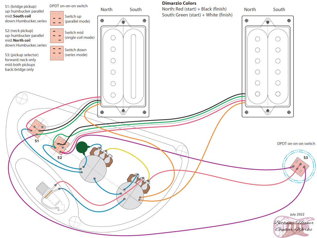
|
|
|
|
Post by newey on Jul 24, 2022 8:54:32 GMT -5
ssstonelover- I debated moving your diagram to the general guitar wiring area, as you did have a question, but on the other hand it seems complete. I may still move it depending on how much discussion it engenders. Your diagram is fine if the DPDT On-On-On switches are as you describe them OR if we are looking from the top of the guitar downward, through the switch (on the one hand, we are looking at the tops of the HBs, OTOH we are looking at the bottoms of the pots, so not obvious which way it was meant to be "up"). But the typical way of drawing a wiring diagram is as if looking from the bottom up, looking at the lugs of the switch as one would wire them. But, OTOH, if this depicts the wiring as usual, from the bottom up, then I have never seen DPDT On-On-On switches that operate as you describe them. I have used plenty of these over the years, and on every one I have ever encountered, the center position is the opposite of your description- Bottom left connects to center, top right connects to center, opposite of how you show it. If the switches are as you describe them, then I wonder where you got them- and I guess it means I will now need to start double checking each one in the future, just to be sure which way it operates. (Although I always test switches before wiring them anyway). The only improvement I can see on your diagram is that, as shown, the split postions leave the unused coil "hanging from hot". Not a deal-breaker, and it can be fixed easily if desired. I can post a diagram once I know for sure that your switches are the oddball ones you describe. Not sure what you mean here; you show the one HB wired "inside out", as our long-time member wolf calls it, so as to select the opposite coil. I wouldn't know who to attribute that to, it's been done forever.
|
|
|
|
Post by ssstonelover on Jul 24, 2022 13:44:08 GMT -5
Hi Newly, Thanks for looking at this. If you want to move the thread that's of course fine, and up to your best judgement most certainly. 1. DPDT On-On-On. Of course there are 2 main types. I have the type I (one) it appears (per multimeter)  As far as switch orientation, these are described as seen from the back of the guitar (assuming x-ray vision!) so floor is 'down' and ceiling is 'up' assuming playing position. Basically I following the nomenclature of the drawing above... It could be confusing as I show the HBs from the front of the guitar....so non-matching to the switches in a sense. No worries, happy to follow any needed convention you prefer. 2. Hanging coils: Sure I'd love to add correction to any needed re-work of the drawing for the sake of clarity and completeness. I've seen this term come up before and probably I've been guilty of missing this before on some older drawings as well. I guess it's something not totally clear to me. I guess a problem that's not a problem (until it is) but can be eliminated for better prevention. 3. Inside out: I love that term! I LOVE it! So funny. Yeah, I suspected I was reinventing the wheel (S1's wiring), so I'm not surprised wolf and others beat me to the punch. Hard to be original when lots of minds are working on the same subjects over time and solving the same issues repeatedly. At least I came to the same functional conclusion.... |
|
|
|
Post by newey on Jul 24, 2022 19:29:10 GMT -5
Of course there are 2 main types. It's the "of course" that throws me, as I've never seen (or heard, until recently) of any "Type 1" On-On-Ons I won't move the diagram since it is correct for the type of switch you have. Others should just be advised that their On-On-On is probably of the other type, and that the switch wiring in the diagram will need to be mirror-imaged accordingly. Re Hanging coils: It's not a problem, only the potential of one, one which may never be an actual problem. The (potential) issue is noise. In theory, a coil wired to the "hot" side with the ground side unconnected could act as an antenna, introducing noise into the signal. The theory is sound, but whether it makes any real-world difference is questionable, and has been debated for years here. Some have done experiments showing no difference in noise with or without hanging coils, but one can't test for every possible electrical environment- maybe that dodgy neon beer sign bewhind the bar where one is playing induces noise hwere the guitar is quiet everywhere else. SInce one can never really be sure, we consider it "best practices" to avoid hanging coils where possible- but there are some designs where it's either not possible to avoid, or where avoiding a hanging coil would mena needing a more complicated switch. Here's how to do it without the hanging coil, although this is mirror-imaged from your switch. Courtesy of Unklmickey, way back when. As he notes, the wiring is the same whether one wants an On-On series/parallel switch, or an On-On-On to add the coil split in the center position: 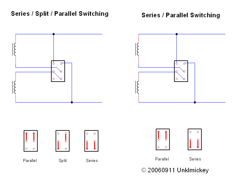 That was wolf's term for it, on his website. ashcatlt calls it "restacking the coils" which is probably more technically accurate. |
|
|
|
Post by ssstonelover on Jul 25, 2022 1:32:58 GMT -5
Hi Newey I made an edit to the original post to alert people to the existence of 2 types of on/on/on DPDT switches, should they want to do this wiring, and said that info is in the replies, so they can make a version of the wiring using the alternative switch as well. Thanks for your explanation of hanging coils and potential pitfulls involving it. Unklmickey's drawing is great, I have gone ahead and flipped it horizontally and rotated it 180 degrees so it accords to my "type 1" switch. Doing that and adding in the DiMarzio wire colors makes it appear there are no hanging coils, or that if there are, they are also present in Unklmickey's diagram too. I also added the "coil restacking" to the drawing, should anyone also want to do the coil splitting I show (N polarity on one HB and S on the other). 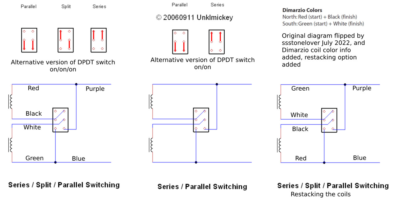 |
|
|
|
Post by ssstonelover on Aug 30, 2022 1:02:46 GMT -5
Edit: Dec 12, 2022. further drawing revision on the post of Dec.12, previous drawing kept for reference purposes.Here is the finalized wiring diagram. I changed the DPDT on/on/on to the type-2 configuration, as it is the more common version, and what I had more of. Wiring was tested today and is functional. I also changed the perspective, per Newey's suggestion to be less confusing for anyone attempting the soldering. 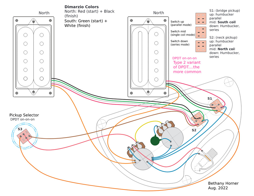
|
|
|
|
Post by ssstonelover on Dec 11, 2022 20:22:20 GMT -5
Well, I spoke too soon as far as final version. I built the last version on the guitar and it works but it failed to give hum cancelling when both pickups were ON and SC split was selected for BOTH, perhaps a small issue. After some reflection it seemed wiring the second switch "inside out" was not totally enough as what we'd really want to see is one of the split coils being RWRP (reverse wound reverse polarity) in relation to each other, like in the analogous situation of the mid pickup of the Strat when combined with either the bridge or neck pickup. Therefore I have reworked the drawing to not only have the 'inside out' feature of selecting the 'other coil', but to ensure RWRP functionality for one of the SC splits when added to the other split. Note 1: The other positions (parallel and series) for the bridge PUP should be unaffected in sound, even with the wires going 'inside out' and reversed compared to the classic examples I copied from previously. Note 2: I also took the liberty to do some drawing cleanup for clarity, and to list all the possible pickup combinations. I show possible coil flow direction (but mainly to keep me straight and to see differences with other coils and pickups). Note 3: as far as what the coil direction really is (clockwise or counterclockwise), it does not matter as long as coils share relative similarities or differences with other coils and pickups in the circuit. Note 4: I'm OK with the last wiring I did (minor issue), but I have another project which should be good for this hum cancelling enhancement, and at that time I'll trial it out....but that won't be right away. I'll report back at that time. If any of you see an issue prior to that time do let me know please. Thanks! 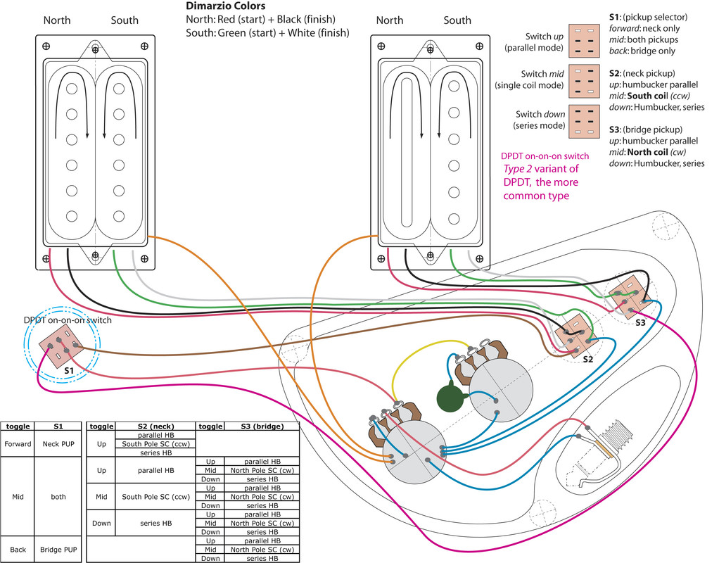 |
|
|
|
Post by newey on Dec 12, 2022 6:47:05 GMT -5
In a humbucker, one coil is wound reverse to the other and is of opposite magnetic polarity, i.e., one coil is RWRP with respect to the other. Thus, if 2 humbuckers are both split to a single coil, selecting the North coil from one and combining it with the South coil of the other will be hum-cancelling. That is the entire purpose of the "inside out" wiring of the one HB.
The RWRP middle pickup in a Strat, when combined with either the neck or bridge, works the same way- it is just a "widely spaced humbucker", i.e., the coils are just further apart.
All of this is subject, however, to the proviso that all bets are off if the pickups are not identical. Manufacturers vary as to which coil is N or S, so with differing pups, one cannot simply assume that combining a slug coil with a screw coil will be hum-cancelling.
So, unless you were using different pickups, the problem was a wiring issue, not a problem with the diagram. When you say it failed to give hum-cancelling, did you test to see which coils were actually active with the splits?
|
|
|
|
Post by ssstonelover on Dec 12, 2022 14:19:16 GMT -5
Hi Newly,
Thanks for the general comments and for the question.
-Both pickups were labelled DiMarzio and have similar wiring colors, but without pulling off the wrapping (something I was unwilling to do) and chasing down the wire connections to see if they were connected identically and were perfectly wired pairs to each other, I can't confirm they were made correctly. All I really know is they are dissimilar models, presumably both real Dimarzio's, are not a matched pair, and were made at different times.
-I did the 'metal object' magnet test in SC mode (switch set to split coil) for the two pickups separately. In one case the pickup responded louder to the South coil, in the other case to the North coil, but in both cases, even when the 'wrong coil' was tapped with a metal object there was still some noise (maybe a shared magnet orientated sideways).
-I also did a 'compass' test to confirm N and S for all coils on both pickups. Nothing strange there, no smoking gun unfortunately.
-I did a resistance test with the bridge pickup and the higher resistance "S" coil is attached when split. For the neck pickup....hard to say, resistance was about the same for both coils even initially, so this test was inconclusive.
My limited exploration has me stumped
-What is very curious is that the combined sound (B + N in SC) is not giving the 'out of phase' of a reverse wired RWRP to a properly wired SWSP (new term: standard wired standard polarity!) pickup, but instead sounds like my 74' Strat (it has no RWRP PUPS to affect position 2 or 4)... In other words something is really fishy and pointing to a 'hidden' wiring issue which is seemingly contradicting the 'screwdriver magnet' test.....strangely...and pointing to the neck pickup possibly.
Further steps:
-I could try the wiring I just drew up or....
-I suppose the most logical thing to do (at least one strong possibility) would be to unwire one pickup entirely (neck for example) from the harness, and then using alligator clips attach one coil at a time to the bridge pickup (to achieve N + B SC mode) on a live guitar hooked up to the amp to work out ideal polarity and coil wind direction, after which the rest of the wiring will fall into place. This will get rid of hidden issues for sure....and would works for dissimilar brands, etc....at least when the wiring can be accessed through the back so the strings are still on!
This does seem alike a lot of work (client will mainly be playing HB mode anyway) BUT between the 2 choices above (and the original wiring) gives quite a few options to try on future guitars....when things don't go swimmingly....
Newly, you may have some more suggestions which I'd love to hear, and I'm sure there is a wealth of practical tips I could chase given the great minds in the group.
|
|
|
|
Post by newey on Dec 12, 2022 23:22:30 GMT -5
My limited exploration has me stumped Your pretty thorough exploration has me stumped as well.  This is expected behavior. The louder coil is the active one, but some signal is also induced in the adjacent coil. You shouldn't need to do all that, but again, I'm stumped so it's a better plan than what I've got ('cause I got bupkis . . .) |
|
|
|
Post by ssstonelover on May 3, 2023 19:22:11 GMT -5
Hi Newey, I found the problem's solution. Basically the way the parallel/split/series is wired on the switches is fine BUT when the second pickup is wired to take the opposite coil (for reverse polarity) for the split (RWRP), the coil direction also has to change and that is something that is not considered in any of the existing wiring diagrams I've seen printed. In other words inverting the 'hot' and 'ground' wire hookups on the second switch finalizes the missing element to get true RWRP between pickups and is the reason all the previous testing came out confusing. Everything tested was fine, but as testing did not check winding direction, just 'start and finish' of coils, it was insufficient. I made the change and the testing came out positive. This diagram reflects that correction. How did I come up with the solution? I was working on another wiring with another brand of pickups series-split-coil-parallel-free-way-PTB and since I knew I might run into this, I did lots of alligator clip testing prior to final soldering, and this was the obvious point to check and there it was. It had nothing to do with pickup brand, etc, just the hot/ground coming off the switch to flip the windings on the coil 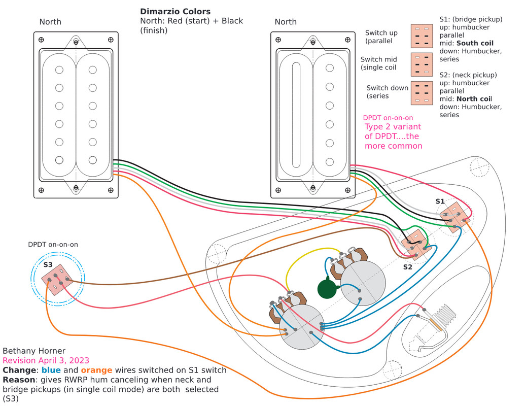 |
|
baruj
Rookie Solder Flinger

Posts: 2
Likes: 0
|
Post by baruj on Aug 4, 2024 8:11:14 GMT -5
Hello, I'm new here. Thanks for sharing the diagram.
Can the switch that selects the pickups be replaced with the 3-way Toggle Switch that comes on all guitars?
|
|
|
|
Post by reTrEaD on Aug 4, 2024 12:14:53 GMT -5
Hello baruj and welcome to GN2. Hello, I'm new here. Thanks for sharing the diagram. Can the switch that selects the pickups be replaced with the 3-way Toggle Switch that comes on all guitars? Yes, the pickup selector switch could be a standard Gibson style toggle (or a 3-way Telecaster style blade switch). However, the switches that perform the local function of each pickup (Series/Single/Parallel) must be DPDT on-on-on switches. |
|
baruj
Rookie Solder Flinger

Posts: 2
Likes: 0
|
Post by baruj on Aug 6, 2024 8:58:59 GMT -5
Thank you very much. I have to assemble this circuit and also one hsh and 5 selector key 
Yes, the pickup selector switch could be a standard Gibson style toggle (or a 3-way Telecaster style blade switch). However, the switches that perform the local function of each pickup (Series/Single/Parallel) must be DPDT on-on-on switche |
|