Post by Yogi B on Nov 5, 2022 23:03:35 GMT -5
(Arguably this could perhaps live in the Amps sub-board, but it is also relevant to tapped pickups.)
The inspiration for this post comes from the following, ostensibly paradoxical, truths:
This is of course not a contradictory difference in behaviour — it's just that we have a variable unaccounted for: the coupling coefficient, k. In the former series case it is assumed the inductors are completely independent, having no linked flux, k = 0; whereas for the latter, adjacent turns within a single coil are assumed to have perfect coupling with k = 1. From the majority of what I have found online, this binary choice — zero or one — is seemingly where a line is drawn, beyond which the influence of k in relating the inductance of a full coil to its subsections is largely either ignored, incomplete, or incorrect.
In calculations pertaining to transformers it is usually assumed that they're ideal, with a coupling coefficient of exactly one, which is probably not too unreasonable since transformers are optimised towards having high efficiency, thus high coupling. Therefore, where it may be more useful to consider intermediate coupling factors is with guitar pickups where: the taps of a single coil have high, but submaximal coupling; and adjacent coils (such as those in a typical humbucker) have low, but non-negligible coupling.
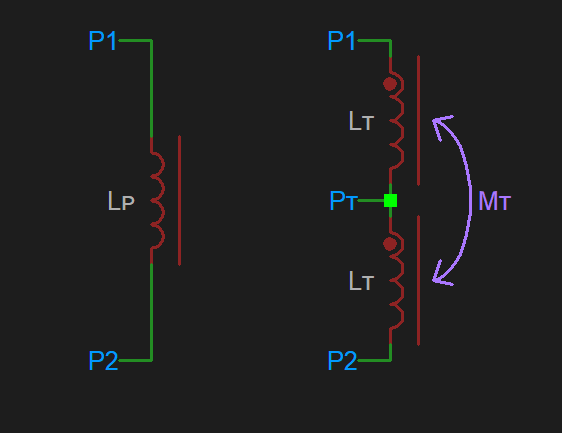
Let's consider an inductor between points P1 & P2: first as a single lumped inductance, LP; and secondly with a centre tap, forming two inductances LT.

The taps have mutual inductance, MT, given by:
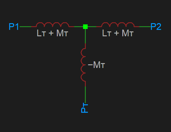
and can be expressed as the following equivalent circuit of three uncoupled inductors:

From this and the initial lumped inductance circuit — noting that the inductance between P1 & P2 must be equal in both cases — we can derive the following:
For cases of taps within an isolated coil, this calculation (or appropriate variation of it) is enough. However, though the above calculation maintains the total inductance, it also has the side effect of altering any mutual inductance which exists between that and any other coil. Therefore (and since the thread title specifically mentions transformers) let's also consider the case where the primary coil is also initially coupled (via coefficient ki) to a secondary coil, related by a turn count ratio, N, such that: LS = LP / N2
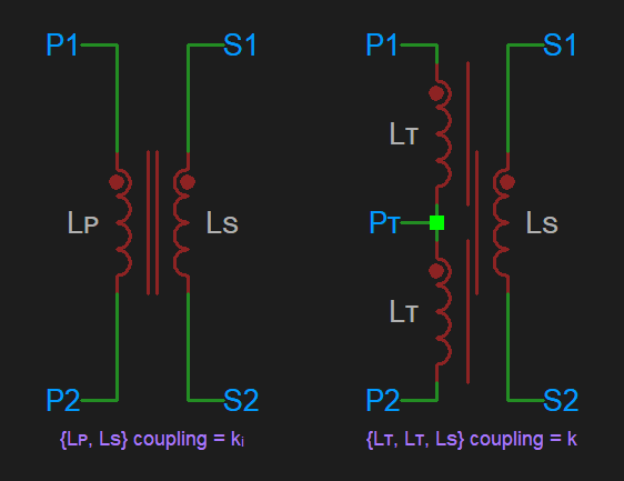
Diagrammatically, for the untapped & tapped alternatives, we have:

Equating the mutual inductances (solely those between the primary and secondary) of the two situations gives:
Solving this quadratic in k gives:
Of which only the positive branch is valid since the phase relationship of the two windings should remain unchanged.
The same methods can be applied to more complex tapping schemes, however the maths quickly gets somewhat out of hand. For example a push-pull output transformer with a centre tapped primary and 16Ω, 8Ω & 4Ω taps on the secondary results in a nonic equation (degree 9 polynomial) — which although reducible to a quintic still may not be a great deal of help, since in general there is no closed form solution to a quintic. Though, since it can be solved numerically using a root finding method of your choice, for reference this equation is:
The inspiration for this post comes from the following, ostensibly paradoxical, truths:
- series inductances add, i.e. given two inductances L1 & L2, the series inductance is L1 + L2 — doubling up identical inductors doubles the total inductance;
- inductance of a (non-saturated, solenoid) coil is proportional to the number of turns squared — doubling the number of turns quadruples the total inductance.
This is of course not a contradictory difference in behaviour — it's just that we have a variable unaccounted for: the coupling coefficient, k. In the former series case it is assumed the inductors are completely independent, having no linked flux, k = 0; whereas for the latter, adjacent turns within a single coil are assumed to have perfect coupling with k = 1. From the majority of what I have found online, this binary choice — zero or one — is seemingly where a line is drawn, beyond which the influence of k in relating the inductance of a full coil to its subsections is largely either ignored, incomplete, or incorrect.
In calculations pertaining to transformers it is usually assumed that they're ideal, with a coupling coefficient of exactly one, which is probably not too unreasonable since transformers are optimised towards having high efficiency, thus high coupling. Therefore, where it may be more useful to consider intermediate coupling factors is with guitar pickups where: the taps of a single coil have high, but submaximal coupling; and adjacent coils (such as those in a typical humbucker) have low, but non-negligible coupling.
Let's consider an inductor between points P1 & P2: first as a single lumped inductance, LP; and secondly with a centre tap, forming two inductances LT.

The taps have mutual inductance, MT, given by:
\def\mul{\mathbin{\mathchoice{\mkern-6mu}{\mkern-6mu}{\mkern1mu}{}}}
M_T = k \mul \sqrt{L_T \mul L_T} = k \mul L_T
and can be expressed as the following equivalent circuit of three uncoupled inductors:

From this and the initial lumped inductance circuit — noting that the inductance between P1 & P2 must be equal in both cases — we can derive the following:
\def\mul{\mathbin{\mathchoice{\mkern-6mu}{\mkern-6mu}{\mkern1mu}{}}}
\begin{aligned}
(L_T + M_T) + (L_T + M_T) &= L_P
\\[1ex]
2 \mul (L_T + k \mul L_T) &=
\\[1ex]
2 \mul L_T \mul (1 + k) &=
\\[1ex]
L_T &= {L_P \over 2 \mul (1 + k)}
\end{aligned}
For cases of taps within an isolated coil, this calculation (or appropriate variation of it) is enough. However, though the above calculation maintains the total inductance, it also has the side effect of altering any mutual inductance which exists between that and any other coil. Therefore (and since the thread title specifically mentions transformers) let's also consider the case where the primary coil is also initially coupled (via coefficient ki) to a secondary coil, related by a turn count ratio, N, such that: LS = LP / N2
Diagrammatically, for the untapped & tapped alternatives, we have:

Equating the mutual inductances (solely those between the primary and secondary) of the two situations gives:
\def\mul{\mathbin{\mathchoice{\mkern-6mu}{\mkern-6mu}{\mkern1mu}{}}}
\begin{aligned}
k_i \mul \sqrt{L_P \mul L_S} &= k \mul \sqrt{L_T \mul L_S} + k \mul \sqrt{L_T \mul L_S}
\\[2ex]
k_i \mul \sqrt{L_P \mul L_S} &= 2 \mul k \mul \sqrt{L_T \mul L_S}
\\[2ex]
k_i \mul \sqrt{L_P \times {L_P \over N^2}} &= 2 \mul k \mul \sqrt{L_T \times {L_P \over N^2}}
\\[2ex]
k_i \times {L_P \over N} &= 2 \mul k \mul \sqrt{{L_P \over 2 (k + 1)} \times {L_P \over N^2}}
\\[3ex]
k_i \times \cancel{L_P \over N} &= 2 \mul k \mul \sqrt{1 \over 2 \mul (k + 1)} \times \cancel{L_P \over N}
\\[3ex]
{k_i}^2 &= {4 \mul k^2 \over 2 \mul (k + 1)}
\\[3ex]
2 \mul {k_i}^2 \mul (1+k) &= 4 \mul k^2
\\[1ex]
0 &= 2 \mul k^2 - {k_i}^2 \mul k - {k_i}^2
\end{aligned}
Solving this quadratic in k gives:
\def\mul{\mathbin{\mathchoice{\mkern-6mu}{\mkern-6mu}{\mkern1mu}{}}}
k = {k_i \over 4} \mul \left(k_i \pm \sqrt{{k_i}^2 + 8}\right)
Of which only the positive branch is valid since the phase relationship of the two windings should remain unchanged.
The same methods can be applied to more complex tapping schemes, however the maths quickly gets somewhat out of hand. For example a push-pull output transformer with a centre tapped primary and 16Ω, 8Ω & 4Ω taps on the secondary results in a nonic equation (degree 9 polynomial) — which although reducible to a quintic still may not be a great deal of help, since in general there is no closed form solution to a quintic. Though, since it can be solved numerically using a root finding method of your choice, for reference this equation is:
\def\mul{\mathbin{\mathchoice{\mkern-6mu}{\mkern-6mu}{\mkern1mu}{}}}
\Bigl(k - 1\Bigr)^2
\mul \Bigl(k + 1\Bigr)
\mul \Bigl(2 \mul k + 1\Bigr)
\mul \Bigl(
k^5
- (2 \mul {k_i}^4 - 6 \mul {k_i}^2 + 1) \mul k^4
- (7 \mul {k_i}^4 - 12 \mul {k_i}^2) \mul k^3
- (9 \mul {k_i}^4 - 6 \mul {k_i}^2) \mul k^2
- 5 \mul {k_i}^4 \mul k
- {k_i}^4
\Bigr) = 0

