|
|
Post by MattB on Dec 31, 2022 9:59:45 GMT -5
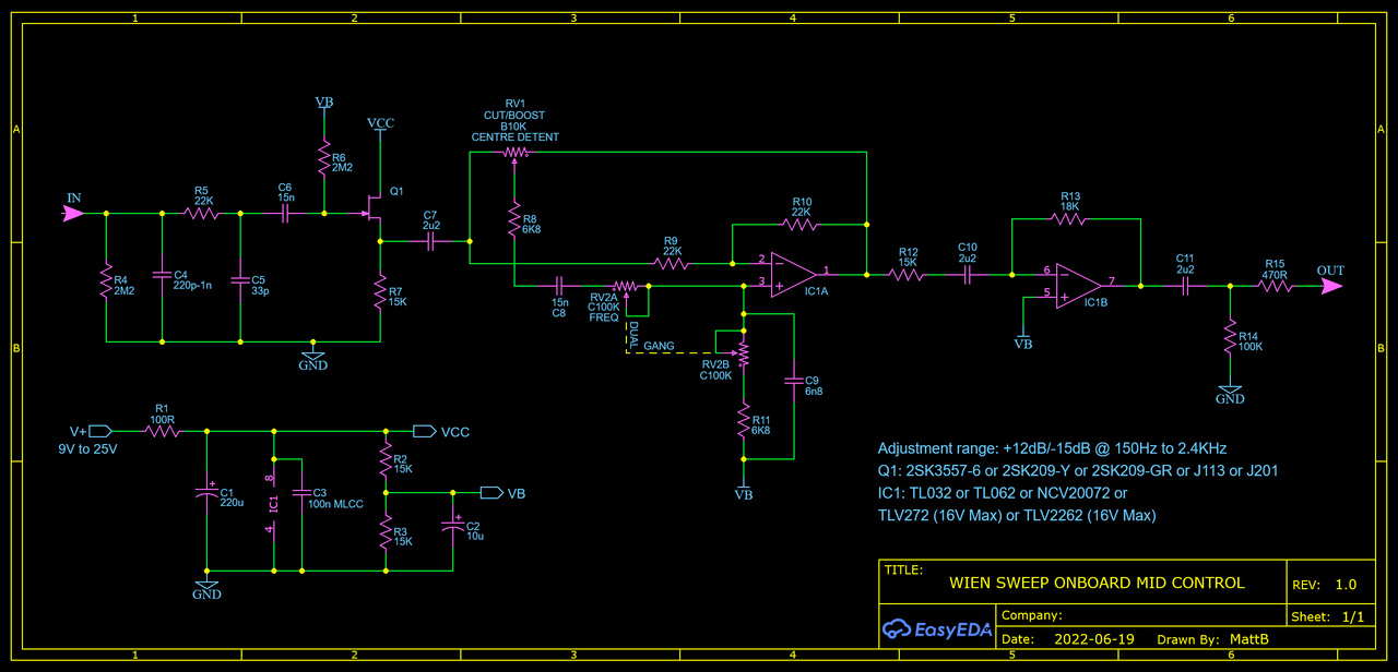
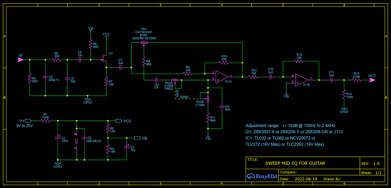
This design is based on a schematic I found in Small Signal Audio Design by Douglas Self.
I added an input buffer so it will work well with passive pickups. Input impedance is a bit over 1Meg. C4 is there to replicate the effect of cable capacitance. With the right sized cap this should let you get close to the sound of the guitar going straight into an amp. R5/C5 are there to keep high frequency noise out of the circuit. They form a low pass filter with a cutoff frequency above 200KHz, so they don't have any effect on the sound. The filter section is built around a single op-amp. The second op-amp is there for three reasons: 1) Because the filter section is inverting, so adding a second inverting stage makes the whole thing non-inverting. I don't think this matters much for a circuit made to go inside a guitar but it does potentially allow some more complex ideas, like different active tone controls for each pickup.
2)To add a very small amount of makeup gain, which compensates for the slight loss from the buffer and even smaller loss from the filter.
3)Because a dual op-amp is the same size as a single, and usually around the same price, so it's worth adding the extra stage even though it doesn't do very much. For more gain, increase R13. 39K would give around 7dB more volume. 82K would be around 13dB extra.
The frequency pot is a dual-gang, and ideally it should be a reverse log taper. On the plots below the yellow line is at 90% of the full pot resistance. You could instead use a normal log taper pot wired backwards, so the highest frequency is at 0 and the lowest is at 10. You can find 9mm sealed dual gang pots fairly cheaply, and I think those are a good choice, especially if you're trying to squeeze an extra pot into a small cavity. The cut/boost pot is a 10K linear. If you aren't including a bypass switch I think a centre detent is a good idea, and in the middle position the filter is flat enough that you really don't need a bypass.
The amount of boost available is slightly affected by the output impedance of the buffer stage. JFETs with a higher output impedance will have a lower maximum. My spice models show over 14dB of boost available with a 2SK3557-6 and around 12dB with a J201. The graphs below were made with the J201 model. Most other JFETs should perform a little better.
The last image shows the output with the cut/boost set to 50%.
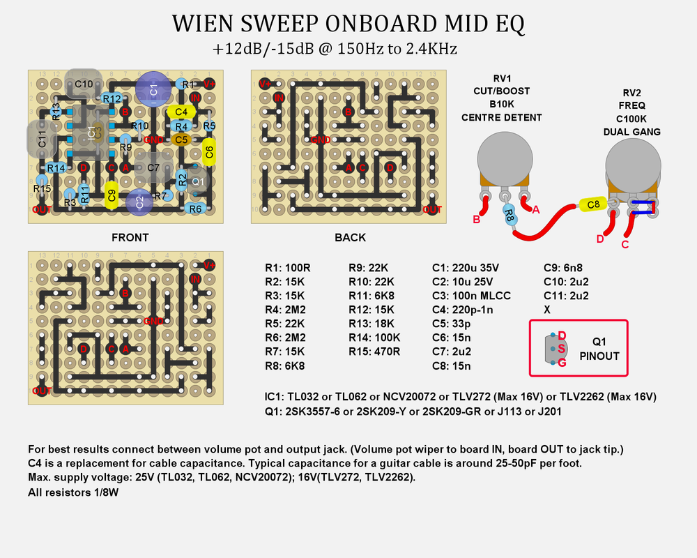
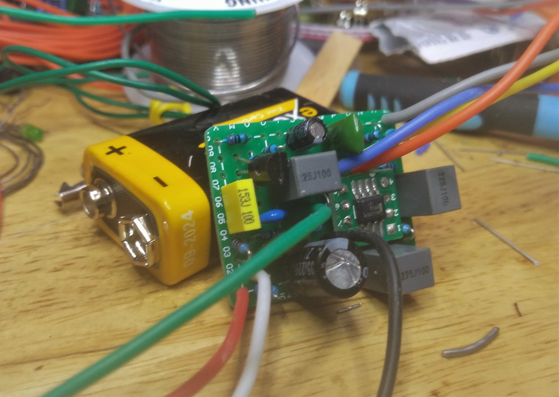 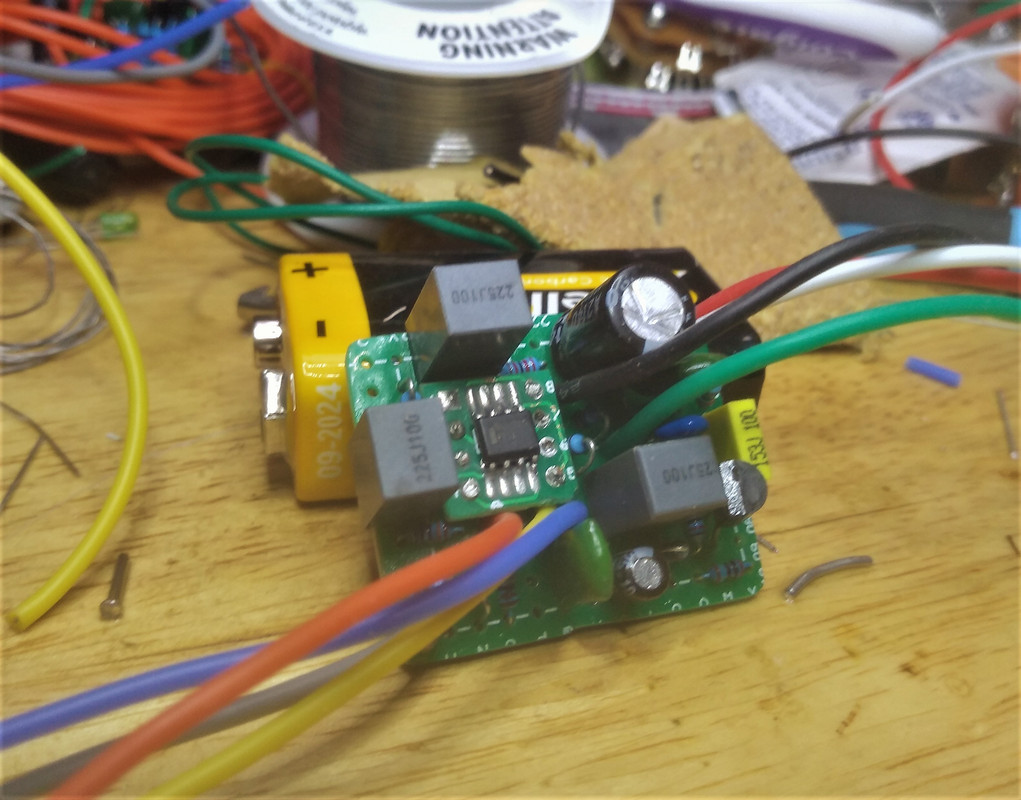 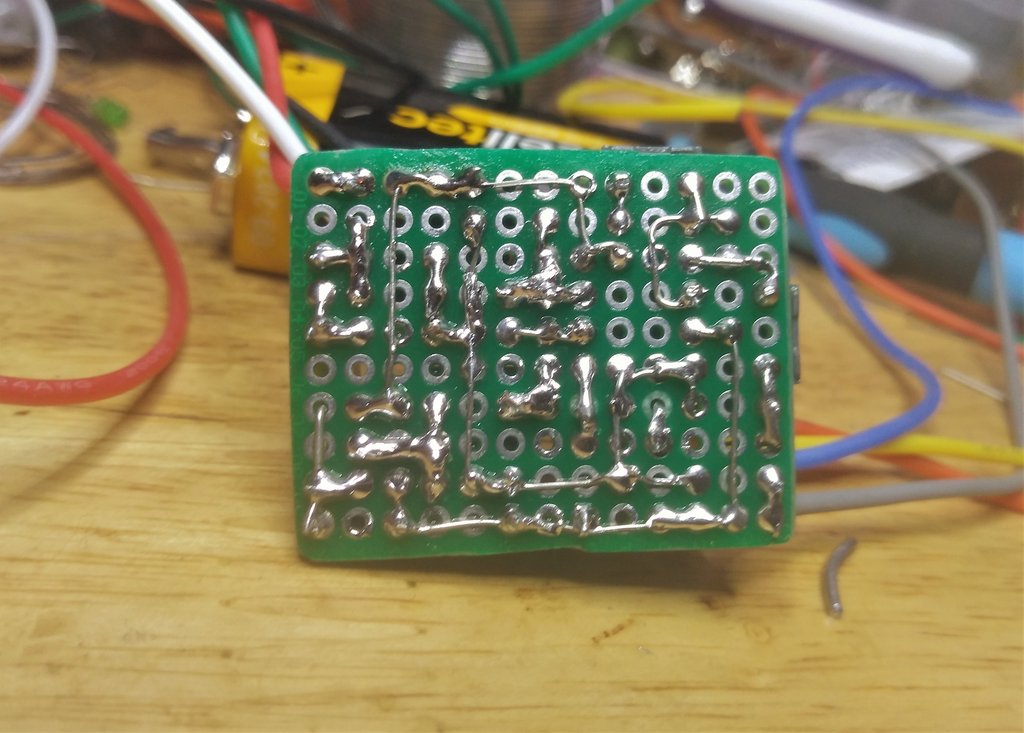  Board size is roughly 22mm*35mm*16mm.
I used an SMT op-amp on an adapter board. A through hole op amp will fit. C3 sits underneath the op amp. I used an axial MLCC cap, which should fit underneath a through hole op amp easily. If not, you can always run it on the other side of the board. It should be placed as close as possible to pin 8 of the op amp. Current draw depends on the specific op-amp and JFET used, but should be no more than 1.5mA, and could be under 1mA.
|
|
|
|
Post by Yogi B on Dec 31, 2022 13:58:16 GMT -5
The filter section is built around a single op-amp. The second op-amp is there for three reasons: - Because the filter section is inverting, so adding a second inverting stage makes the whole thing non-inverting. I don't think this matters much for a circuit made to go inside a guitar but it does potentially allow some more complex ideas, like different active tone controls for each pickup.
- To add a very small amount of makeup gain, which compensates for the slight loss from the buffer and even smaller loss from the filter.
- Because a dual op-amp is the same size as a single, and usually around the same price, so it's worth adding the extra stage even though it doesn't do very much.
Excepting the first point about the making it overall non-inverting (which even in the case of separate controls per pickup doesn't matter so long as they're all non-inverting), I'd use the second op-amp to replace the JFET input buffer. That gets rid of the inherent loss of the JFET buffer and ought to reduce losses caused by the filter, due to having a lower output impedance than the JFET. Ideally, ideally, it'd be a 80% reverse log taper (AKA reverse 20% log taper), that'd give closer to the centre frequency of 600Hz at mid turn. A 200k or 250k value pot with appropriate parallel resistors (to keep the frequency range roughly equivalent) should get closer. Those still might be tough to find as a dual-gang, so adding parallel 100k resistors to the existing 100k pot and halving the impedances of the other frequency affecting components (R8, C8, R11, C9) is likely the most workable solution. |
|
|
|
Post by MattB on Dec 31, 2022 14:38:42 GMT -5
Ideally, ideally, it'd be a 80% reverse log taper (AKA reverse 20% log taper), that'd give closer to the centre frequency of 600Hz at mid turn. A 200k or 250k value pot with appropriate parallel resistors (to keep the frequency range roughly equivalent) should get closer. Those still might be tough to find as a dual-gang, so adding parallel 100k resistors to the existing 100k pot and halving the impedances of the other frequency affecting components (R8, C8, R11, C9) is likely the most workable solution. I have to admit this is one circuit I don't understand as well as I'd like to. I did model it in spice, but then I built it straight from the schematic without spending any time tweaking it. When I next have some free time I'll probably work on it some more. |
|
|
|
Post by JohnH on Dec 31, 2022 15:00:52 GMT -5
Hi Matt
Thanks for posting this and I think its great! Its a useful device and you presented it to us really well so that anyone can have a go.
cheers
John
|
|
|
|
Post by Yogi B on Dec 31, 2022 18:58:33 GMT -5
Ideally, ideally, it'd be a 80% reverse log taper (AKA reverse 20% log taper), that'd give closer to the centre frequency of 600Hz at mid turn. A 200k or 250k value pot with appropriate parallel resistors (to keep the frequency range roughly equivalent) should get closer. Those still might be tough to find as a dual-gang, so adding parallel 100k resistors to the existing 100k pot and halving the impedances of the other frequency affecting components (R8, C8, R11, C9) is likely the most workable solution. I have to admit this is one circuit I don't understand as well as I'd like to. If we elide the active component, underneath we have the bandpass filter formed by R8, C8 & RV2A in series with the signal, followed by R11, C9 & RV2B to (virtual) ground. Though purely passively the result would look quite different (significant insertion loss, lower Q, and the typical 6dB/octave roll off in the stop bands), the corner frequencies are the same. As such we can calculate the centre frequency as: f_c = {1 \over 2 \pi \sqrt{(R_8 + R_{V2A})(R_{11} + R_{V2B})} \sqrt{C_8 C_9}}You could go around the houses to calculate the min & max centre frequencies, then the (geometric) mean of those, then work backwards to find the resistance that gives that frequency. However, with the resistance of both branches being equal and the capacitors being constant, it just boils down to finding the geometric mean of the min & max resistances i.e. sqrt(6.8k × 106.8k) = 26.949k, in other words the 6.8k fixed resistors plus approximately 20k from the potentiometer gangs. |
|
|
|
Post by sumgai on Jan 1, 2023 13:00:32 GMT -5
I have to admit this is one circuit I don't understand as well as I'd like to. Or, Yogi's post notwithstanding, you could simply look up "parametric equalizer", and learn everything you might wish to know about this circuit's basics. Nothing fancy here folks, just some common ideas melded together. In fact, before I left the Uncle Sam's Army in 1971, I built a couple of these things to cover 3 or 4 frequency bands. At the time, my intention was to use them as pre-amps for stereo systems, but it turned out they also worked just dandy as front-ends for guitar amps. Now that I think about it, Gibson's LAB series of amplifiers, introduced in the early 70's, had this feature. Might not be the very first mass-produced guitar (or bass) amp to do it, but certainly in the running for "lead dog". Since then, countless bass amps have included this feature, and I'm sure some guitar amps somewhere are including it as well. And to put paid to it, just about every PA mixing unit costing more than a C-note is using this idea in each Mic channel. That should give you some idea of just how pervasive this idea is in the pro music field. BTW, for a "Fender" feel/tone from nearly any guitar, try notching the signal at 300Hz. Experiment to taste.  HTH sumgai |
|
|
|
Post by MattB on Jan 2, 2023 6:21:42 GMT -5
One thing I forgot to mention: As I said, C4 is a replacement for cable capacitance. If this circuit is placed after the volume control, turning the volume down will cut some high end, because the series resistance of the pot together with C4 forms a low pass filter. In other words, it will behave just like a real guitar cable.
If you don't want to lose treble as the volume is turned down, wire C4 across the outer lugs of the volume pot instead of on the board. This will sound exactly the same with the volume at 10, and won't cut high end as the volume control is turned down.
If we elide the active component, underneath we have the bandpass filter formed by R8, C8 & RV2A in series with the signal, followed by R11, C9 & RV2B to (virtual) ground. Though purely passively the result would look quite different (significant insertion loss, lower Q, and the typical 6dB/octave roll off in the stop bands), the corner frequencies are the same. As such we can calculate the centre frequency as: f_c = {1 \over 2 \pi \sqrt{(R_8 + R_{V2A})(R_{11} + R_{V2B})} \sqrt{C_8 C_9}}You could go around the houses to calculate the min & max centre frequencies, then the (geometric) mean of those, then work backwards to find the resistance that gives that frequency. However, with the resistance of both branches being equal and the capacitors being constant, it just boils down to finding the geometric mean of the min & max resistances i.e. sqrt(6.8k × 106.8k) = 26.949k, in other words the 6.8k fixed resistors plus approximately 20k from the potentiometer gangs. Thanks, this is a very clear explanation, and it's exactly the sort of thing I want to be able to work out for myself.
Hi Matt Thanks for posting this and I think its great! Its a useful device and you presented it to us really well so that anyone can have a go. cheers John Thanks John. After using it for a while I'm very pleased with the way it sounds. At the highest frequency setting it cuts enough treble that I can live without having a separate regular tone control, so the need for two pots isn't as impractical as I thought it would be. |
|
|
|
Post by Yogi B on Jan 3, 2023 2:01:41 GMT -5
Now that I think about it, Gibson's LAB series of amplifiers, introduced in the early 70's, had this feature. Might not be the very first mass-produced guitar (or bass) amp to do it, but certainly in the running for "lead dog". Since then, countless bass amps have included this feature, and I'm sure some guitar amps somewhere are including it as well. And to put paid to it, just about every PA mixing unit costing more than a C-note is using this idea in each Mic channel. That should give you some idea of just how pervasive this idea is in the pro music field. Also worth a specific mention are the designs used within JHS's Haunting Mids & Catalinbread's Varioboost (I've brought these up before, in another thread, though at the time missing what they actually are). Both use an extra op-amp to boost the Q, but go about it in differing ways, with each variation having its own advantages. The Varioboost includes amplification of the signal going from the wiper of the cut/boost pot, via the bandpass filter, and into the non-inverting input of the existing op-amp. When set to the boost side, this extra amplification equates to an increase in positive feedback, thus causing an exaggeration of the existing peak. On the cut side, we're instead dealing with a differential amplifier: so, as extra gain compensates for the insertion loss of the passive filter increasing the peak of the bandpassed signal (at the non-inverting input) towards the level of the 'raw' signal (at the inverting input), the difference between input signals is decreased leading to deepening the notch within the output. The placement of the amplifier has a bonus advantage that it also acts as a buffer between the cut/boost pot and frequency pots. This can otherwise cause some interactivity between the controls during the upper end of the frequency range (i.e. when the freq pots are at their lowest resistance). (Though this side-effect can be reduced by making the cut/boost pot be as small in value as is reasonable compared with the values in the BPF, a buffer eliminates the issue altogether.) The Haunting Mids takes the Wien bridge and directly wraps it around the additional op-amp, this creates an active bandpass filter wherein (once again) the Q can be varied by varying the amount of positive feedback. (Also note: since this active bandpass is inverting, the action of the cut/boost pot is reversed.) The key difference is the locally of this approach to the bandpass filter itself, rather than the surrounding circuit — this enables the pedal's HI/LO switch to significantly increase the Q, but without excessively raising the amplitude of the peak, by simultaneously reducing the signal level going to the non-inverting input of the existing op-amp (this also likely helps prevent the circuit from becoming an oscillator). |
|
|
|
Post by sumgai on Jan 3, 2023 12:22:04 GMT -5
Yogi, ya got me! I'd never heard of those circuit designs, at least not by name. Over the course of my time sitting at the workbench, I may have seen them "in situ", without them being the actual culprit that I was torturing with my soldering iron at the time. Another thing I remembered..... these designs are also called "state variable filters", though the term seems to be somewhat falling out of use. Still and all, Wikipedia has a good page, with simplified math and example component values, to show us what's what: State Variable Filters, ala WikipediaHTH sumgai |
|
|
|
Post by Yogi B on Jan 4, 2023 3:51:57 GMT -5
Yogi, ya got me! I'd never heard of those circuit designs, at least not by name. Over the course of my time sitting at the workbench, I may have seen them "in situ", without them being the actual culprit that I was torturing with my soldering iron at the time. Well they are only somewhat minor variations upon what is already presented here, it's just interesting seeing what can be done without redesigning around an entirely different topology. Anyway, the Varioboost schematic can be found over on freestompoxes, as noted in the discussion there it's also essentially the same circuit variation as used in the Boss Metal Zone mids control. Though note the plots of the Metal Zone's response shown later appear to have been simulated from the same circuit as the Varioboost and accidentally include the effects of the added gain (the 'extra' op-amp in the Metal Zone is used only as a unity gain buffer), so in reality both circuits have similar Q at maximum cut/boost (around 1.4). The schematic for the Haunting Mids can be found in the build docs for PedalPCB's Maleficent Mids and/or build docs for FuzzDog's Spooky Mids V2I'd argue that's a separate family, but it is certainly another way of getting a bandpass filter (one with as much tweakage as one could reasonably hope for) with which you replace the Wien bridge. Fun fact: seemingly, it appears that before the current clones of the Haunting Mids there was a 'workalike' circuit in use by both. See: FuzzDog's original Spooky Mids; and for PedalPCB, the only evidence I found was a build over at the MadBeanPedals Forum. Though 'workalike' may very well be pushing it, at first blush I'm not at all convinced it functions anything that alike (well, I mean there's still an egg, but scrambled when we're after sunny side up) — but I digress: three guesses what filter topology the 'workalike' used. |
|
|
|
Post by MattB on Jan 6, 2023 12:14:41 GMT -5
Excepting the first point about the making it overall non-inverting (which even in the case of separate controls per pickup doesn't matter so long as they're all non-inverting), I'd use the second op-amp to replace the JFET input buffer. That gets rid of the inherent loss of the JFET buffer and ought to reduce losses caused by the filter, due to having a lower output impedance than the JFET. I took a closer look in LTSpice. The losses with a J201 are actually bigger than I thought. 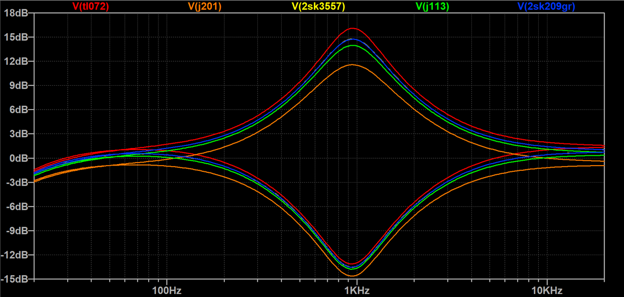 This shows maximum boost and cut for 4 different JFETs in the circuit above, plus one where the JFET is replaced by a TL072 buffer. I have a few different J201 models- this one performs slightly worse than the one I previously used. The line for the 2SK3557 is hidden behind the 2SK209.
The op amp buffer is clearly an improvement, and if I do rework this circuit I'll probably go with that, but for now I'm going to settle for un-recommending the J201 and re-labeling the diagrams. The Spice plot below was made using the same circuit, but with a J113 in place of the J201.
  Well they are only somewhat minor variations upon what is already presented here, it's just interesting seeing what can be done without redesigning around an entirely different topology. A couple more variations by Douglas Self, again from Small Signal Audio Design. Both use only a single gang pot for frequency, which is nice, but Q varies quite a bit. The Spice plot is the three op amp version. 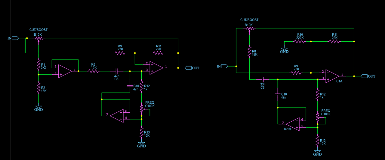 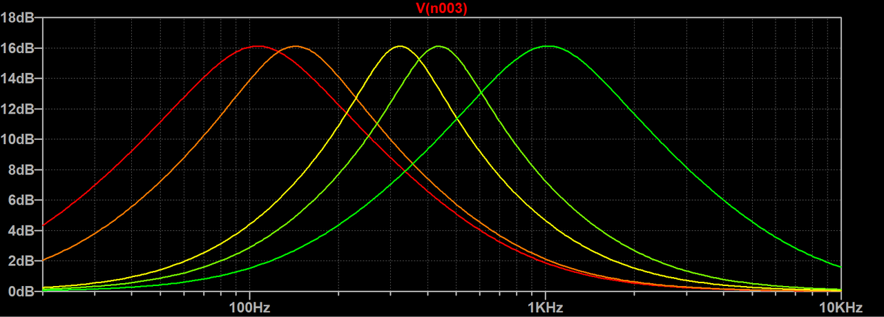 |
|


