|
|
Post by stevewf on Mar 2, 2023 4:10:05 GMT -5
Here's an attempt at getting my SS Tele to do series instead of parallel, and include a kill switch. Comments/corrections/etc requested. WHATI wanted a 3-way switch, but position#2 should give a series connection instead of the usual parallel. Further, position#2 (serial) should use high-value pots to avoid dulling of the sound, while the other positions, being single coil, should use lower-value pots to avoid shrillness. I wanted a momentary kill switch, which is to be mounted between the knobs (in a newly-drilled hole in the control plate). I also wanted to avoid any hanging coils. Treble Bleed required. HOW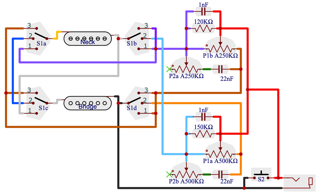 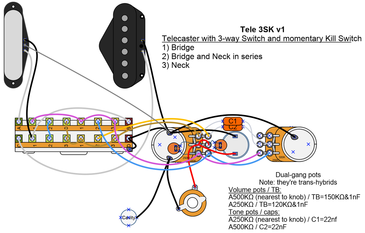 So I got a and a momentary switch. And a 4P3T blade switch because I couldn't see how to get the desired features without one. Likewise, I couldn't see how to use single-gang pots for this. So for the pots, I doctored a pair of Bourns dual-gangers: starting with a 250K/250K dual-gang and a 500K/500K dual gang, I ended up with a mixed pair: a 250K/500K dual-gang and a 500K/250K dual gang (the "top" wafer one one pot is 250K, while the top wafer of the other pot is 500K). I would have preferred a pair of identical 250K/500K pots, but I settled for the cross-mixed pair because while it's pretty easy to swap the "bottom" wafers, it's pretty difficult to swap the top ones (requires destruction of parts). WHYIt might seem like a shame to discard the good ol' parallel setting, but on this guitar (Squier Classic Vibe 50s Telecaster, DiMarzio Black Velvet in the neck, Twang King in the bridge), the parallel sounds very similar to neck-alone. That's why I wanted to use "serial instead" rather than "serial also". CAVEATI bought two of the 4P3T selector switches, and both had problems. The bushing that centers the switch's spindle in the frame gets pulled out of place by the springiness of the detente. This causes lots of play in the switch and a mushy feel. I added a snap ring to help, but it still doesn't feel like a genuine Fender or Oak-Grigsby. Only 4P3T I could find, though. READY?Before I turn on the soldering iron, anybody see any problems, or ways to improve? Thanks! |
|
|
|
Post by Yogi B on Mar 2, 2023 8:10:33 GMT -5
I also wanted to avoid any hanging coils. In order of preference, the options for deselecting a coil go something like: - completely disconnected from the output,
- hanging from ground,
- shunted to ground,
- shunted to hot / hanging from hot.
Therefore, when possible, it would be preferable to leave a coil hanging from ground (as is done almost universally within stock wirings), rather than shunting a coil. As for the last two, there's not really a clear winner.
Given that switching A, A×B, B can be done (disconnecting one coil & having the other hang from ground) with just two poles and switching between 250k/500k can also be done with two poles. With a four pole switch, I'd keep those concerns separate — treating them as distinct modules, the fact that they're being switched simultaneously just as coincidence, rather than reinventing some new solution. If wanting to use a standard Tele switch, and not caring about picking different a tone cap / treble bleed components between series & single coil, then you could just assign each pickup its own set of 250k pots and switch the collective pickup/pots as a single unit (as we discussed in the 3-way + Global Series thread).
I've added either a nut or a stack of washers between the lever and the plastic rotor in an attempt to remedy the same issue on 5-way switches. It maybe helped a little, but to have any great effect I felt would require too much pressure upon the rotor and/or wafer. I might try a snap ring / circlip in future. |
|
|
|
Post by stevewf on Mar 2, 2023 12:47:02 GMT -5
In order of preference, the options for deselecting a coil go something like: - completely disconnected from the output,
- hanging from ground,
- shunted to ground,
- shunted to hot / hanging from hot.
Thanks for that list, Yogi. This forum is the place I'm most likely to take advice by rote, so I'm ready to adopt that list without question. Still, for curiosity... any words to back up preference for hanging from ground rather than shunting to ground? I smell another learning moment for me here. I didn't see how switch the coils as mentioned; I kept ending up with a coil hanging from hot. Anyone offer a quick diagram? Specifically of A, AxB, B as described by Yogi above? Here's a try a showing the problem:  The spring-loaded detente mechanism creates room for the brass bushing, allowing the latter to slip out of place. This causes looseness of the spindle within the frame. On this one, I chose to add a snap ring to the outside. My hope was to reduce the free space for the bushing. Adding a snap ring on the outside, if possible, should avoid using the wafer for supplying pressure. My new snap ring is the wrong size; it won't close, and it fails to do the job completely, so I'll try to get another today.  Even with a correctly sized ring, there'll be inherent problems - that spindle, well, spins, and moves the snap ring with it. There'll be friction and wear. Might be better applied internally, but that means busting the rivets... maybe I'll end up doing that. |
|
|
|
Post by sumgai on Mar 2, 2023 13:26:56 GMT -5
I didn't see how switch the coils as mentioned; I kept ending up with a coil hanging from hot. Anyone offer a quick diagram? Specifically of A, AxB, B as described by Yogi above? Briefly..... This diagram has been in the Schematics sub-forum for a long time, and every so often, it gets dusted off and reposted for those in need. That would be you, Steve.  We have here a 4 way diagram giving both series and parallel. But the easy part is, simply remove the parallel portion of the circuit, and we're good to go. (IOW, skip the wiring for Position 2.) 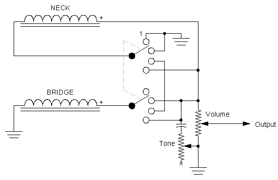 For those viewers who might be thinking to themselves that this could be done on a standard Tele switch, I'm sorry to say that no, it won't work. A standard switch is what we call "shorting" - as it moves from one position to the next, it "shorts" terminals 1 and 2, or terminals 2 and 3. What we need here is a "non-shorting" contraption, as shown in the diagram. A shorting switch, it should now be obvious, will not allow for a series connection at all. I'm sure viewers can figure out why, but if there are questions, just ask. For further discussion on the above schematic, please visit here. HTH sumgai |
|
|
|
Post by stevewf on Mar 2, 2023 17:24:47 GMT -5
Briefly..... This diagram has been in the Schematics sub-forum for a long time, and every so often, it gets dusted off and reposted for those in need. That would be you, Steve.  We have here a 4 way diagram giving both series and parallel. But the easy part is, simply remove the parallel portion of the circuit, and we're good to go. (IOW, skip the wiring for Position 2.)  [...elided by stevewf...] [...elided by stevewf...]For further discussion on the above schematic, please visit here. Yay, thanks! I knew it'd be here (and for a long time), but my search terms were not zeroing in on it. |
|
|
|
Post by newey on Mar 2, 2023 19:02:06 GMT -5
A shorting switch, it should now be obvious, will not allow for a series connection at all Wait a sec. A std 3-way Tele switch is not a shorting switch, only 5-way switches are shorting. And some series settings are also possible with a regular 5-way. although most involve dead or redundant positions. There is also the Deaf Eddie HS scheme, which uses a regular 5-way and gives the SC Bridge in series with one coil of the neck HB, with the full neck HB at the same time. What's wrong with this, using a std. Tele 3-way?  (Granted, bridge does hang from hot) |
|
|
|
Post by sumgai on Mar 3, 2023 1:07:19 GMT -5
A shorting switch, it should now be obvious, will not allow for a series connection at all Wait a sec. A std 3-way Tele switch is not a shorting switch, only 5-way switches are shorting. I spoke out of turn... mea culpa. Absolutely nothing! Additionally, it doesn't require a "course correction" in order to nullify the hanging hot issue, it simply never invokes the problem in the first place. BONUS! No it doesn't. The only permanent connection is to ground (return), not one to ground and one to hot (as shown on my diagram). IOW, you show both pup positive leads being switched as needed, and thus there are no hanging hots with which to deal. In short, I didn't see this one coming, so a Tip Of The Hatlo Hat to you, grasshopper, for you have finally snatched the pebble from my hand! HTH sumgai |
|
|
|
Post by Yogi B on Mar 3, 2023 1:10:47 GMT -5
In order of preference, the options for deselecting a coil go something like: - completely disconnected from the output,
- hanging from ground,
- shunted to ground,
- shunted to hot / hanging from hot.
Thanks for that list, Yogi. This forum is the place I'm most likely to take advice by rote, so I'm ready to adopt that list without question. Still, for curiosity... any words to back up preference for hanging from ground rather than shunting to ground? The argument against shunting is that in allowing a current to flow through the coil we're allowing an opposing magnetic field to develop, in addition we're also wasting energy via heating of the wire. The latter is probably negligible and the former more important with neighbouring coils. (The list is for the general case, in the case of separate neck & bridge pickups the difference between the two shouldn't be as major.) The only possible disadvantage I can think of for hanging from ground is capacitive coupling, allowing a small amount of (treble) signal to bleed through to the output. This issue is common to either form of a hanging coil, but ought to be much less of a problem in the hanging from ground case due to the dimensions of the 'plates' involved: HfG we're concerned with the capacitance between the pickup's unconnected hot wire and the hot output, both of those conductors should be fairly minimal in area and are unlikely to be in close proximity except where they meet at a switch; whereas HfH we're concerned with the capacitance between the pickup's unconnected ground wire and ground, which includes all of the shielding — a much larger area (and often much closer e.g. in the case of screened wires). : What's wrong with this, using a std. Tele 3-way?  (Granted, bridge does hang from hot) Nothing's wrong with it (including that the bridge does not hang from hot!) |
|
|
|
Post by stevewf on Mar 4, 2023 3:20:41 GMT -5
Nice. It's going into the updated version, posted soon, thank yous!
PS - I think that in newey's version, rather than any coil HfH, we only have the neck HfG in position#3.
|
|
|
|
Post by stevewf on Mar 4, 2023 11:07:19 GMT -5
Here's a pair of revamped drawings. I've tried to incorporate Yogi B's suggestions at un-spaghetti-ing the 4 poles of the 3-way as well as newey's neat design for poles a&b of that same 3-way. I did swap the bridge and neck in comparison with newey's (i.e. the bridge hangs from ground when it's not selected). I have question at the bottom of this post concerning the wiring diagram... 1) Bridge (250KΩ vol&tone) 2) Bridge in series with Neck (500KΩ vol&tone) 3) Neck (250KΩ vol&tone) Momentary kill switch in any position
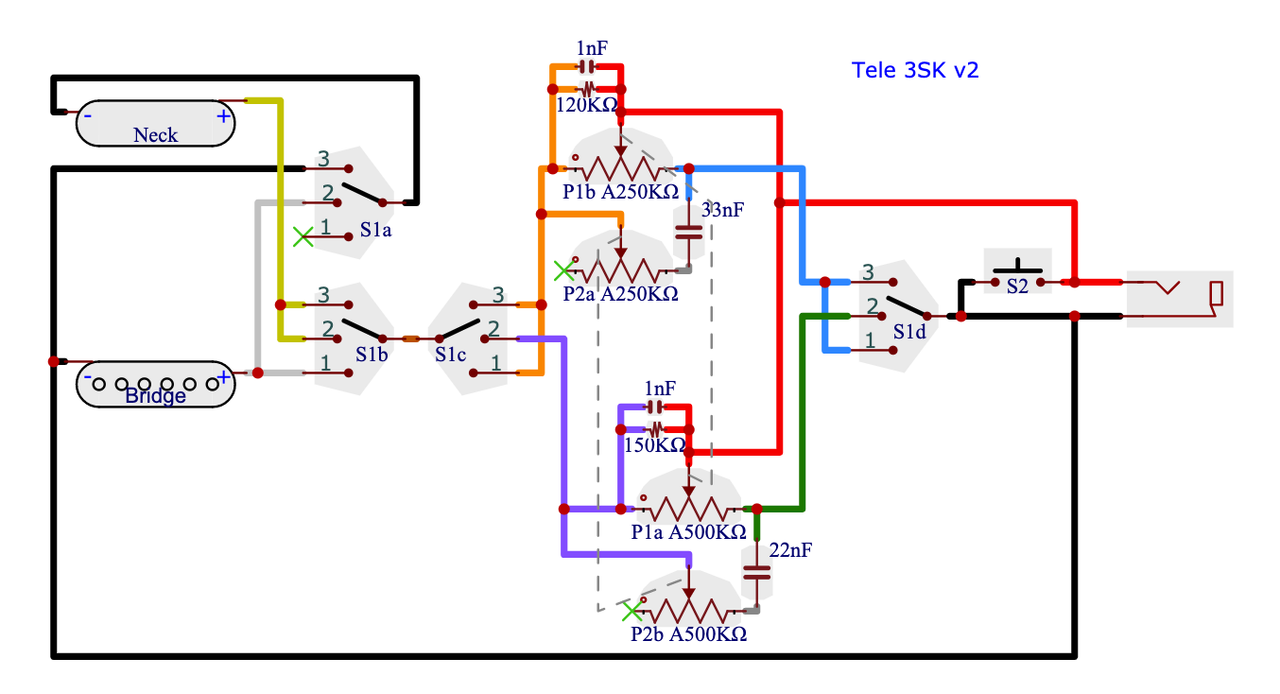
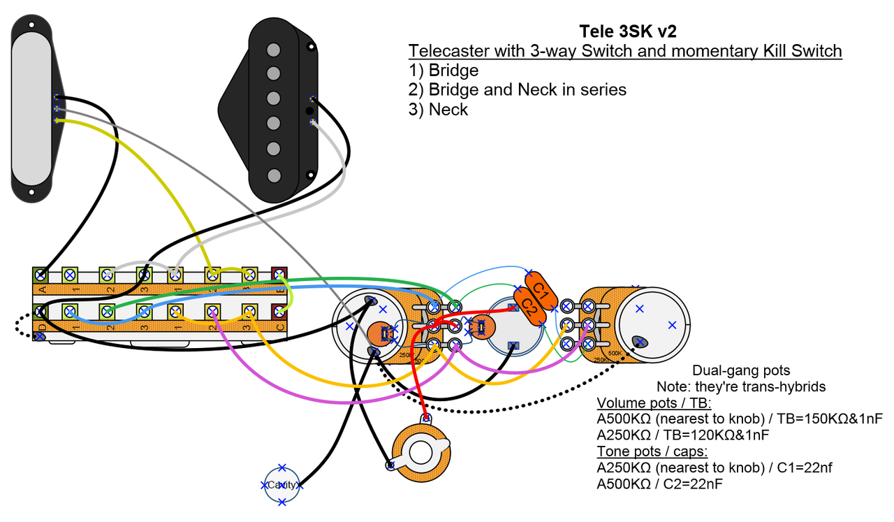 [Note: wiring diagram updated to correct tone cap placements] [Note: wiring diagram updated to correct tone cap placements]
Here's my wiring Q: should I indeed ground the 3-way switch and the tone pot (see the dotted wires)? It's all inside a shielded cavity, lined with grounded copper tape. |
|