devman01
Rookie Solder Flinger

Posts: 3
Likes: 2
|
Post by devman01 on Mar 8, 2023 16:56:48 GMT -5
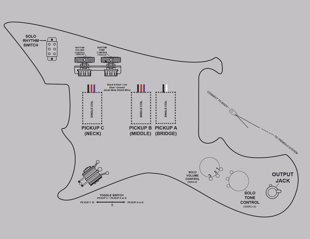
 Trying to wire up an old Yamaha SG3 with some third party parts. The wiring should be similar to a Jaguar guitar (due to the tone roller pots). The pickups im using are some old Kawai pickups from a Domino California Rebel. I found a post on this site that mentioned that the Red and Black wires are the coils and the blue is the ground, or most likely a shield wire, not signal carrying. I don't really know the differences so any help would be very appreciated. I've been very hyper fixated on wiring this thing up so anything would help. |
|
|
|
Post by Yogi B on Mar 9, 2023 13:18:41 GMT -5
I found a post on this site that mentioned that the Red and Black wires are the coils and the blackblue is the ground, or most likely a shield wire, not signal carrying. I don't really know the differences so any help would be very appreciated. I'm guessing the post you mention could be from the 70s Japanese short scale guitar wiring thread wherein we were assuming the blue wires were shield wires. Whichever the shield wires in fact are, they connect to the metal chassis of the pickup and should always be wired up to any other grounding of metal hardware (e.g. the tremolo/bridge ground, potentiometer casings, switch chassis, etc.) and ultimately the sleeve (ground) connection of the jack socket. The intent of doing so is to reduce noise. Contrastingly, the signal wires are just the connections to either end of the actual pickup coil. As such, there isn't really an inherent reason as to which one ought to be the ground wire, aside from to fit in with whatever convention is established by the other pickups on the guitar. That is, connecting the leads one way around will result in the combination with another pickup being in phase, the two signals reinforcing — whereas reversing the signal wires of one pickup will reverse the phase relationship, resulting in the pickups being out-of-phase, diminishing the combined signal. Additionally, and as is the case with series wiring combinations, it is not necessarily true that either end of a particular coil is connected directly to ground.
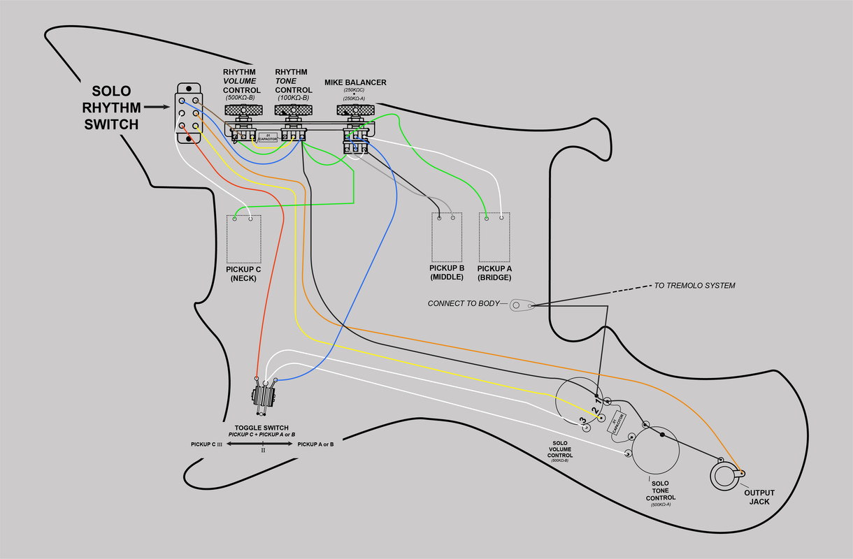
The service manual for the SG-3/SG-2/SB-2 can be found on the Yamaha Musicians Forum — the wiring diagram for the SG-3 can be found on page 12 (the 22 nd image, they're in reverse order). In your parts layout you are missing the A/B series blend control (the "Mike Balancer"), is this an intentional omission? |
|
devman01
Rookie Solder Flinger

Posts: 3
Likes: 2
|
Post by devman01 on Mar 9, 2023 14:56:43 GMT -5
  I did see the original schematic from the manual. I actually re-made it to be more readable but I can't confirm that it would work since the original schematic is hard for me to dissect. I have no experience in wiring whatsoever (if you can't tell). If ur able to confirm its correct I would greatly appreciate it! |
|
devman01
Rookie Solder Flinger

Posts: 3
Likes: 2
|
Post by devman01 on Mar 9, 2023 14:59:00 GMT -5
I purposely omitted the mike balancer from my first uploaded schematic because I thought it would give me trouble and would be easier for someone online to help me out wiring it up.
|
|
|
|
Post by Yogi B on Mar 11, 2023 13:15:32 GMT -5
I purposely omitted the mike balancer from my first uploaded schematic because I thought it would give me trouble Well it does certainly introduce quirks to the behaviour of the circuit. The additional resistance it introduces in series with pickups A & B means that in the middle toggle position, only at the very extremes will you get a 50/50 blend of pickup C and pickups A/B, throughout the rest of the range you'll mostly be hearing just pickup C. It'll also be 'interactive' with the "solo" tone control similar to the effects of '50s wiring, but to a lesser extent. I did see the original schematic from the manual. I actually re-made it to be more readable but I can't confirm that it would work since the original schematic is hard for me to dissect. I have no experience in wiring whatsoever (if you can't tell). If ur able to confirm its correct I would greatly appreciate it! In your recreation there are a couple of issues I can see. The first is that the two gangs of the balancer potentiometer should most likely be the other way around: on the physical parts the top gang (closest to the knob) is usually the 'A' taper, therefore meaning the 'C' taper is the other ( bottom) gang. The second is, with that particular drawing of a toggle switch, the output terminals are on the other side of the switch from the input terminals. You currently show the output (white wires) coming from the chassis ground terminal. (In some cases the inputs & output(s) are on the same side, but the giveaway is that the ground terminal is always closest to the middle of the switch. It's usually pretty obvious with the actual part in hand, but can be confusing with a 2D view.) The third and final isn't truly a problem, and is the fault of the original diagram, but I'd reroute the white wires between the toggle switch, "solo" volume & "solo" tone. I'd connect the wire from the tone pot directly to lug 3 of the volume, instead of running a second wire all the way to the switch. |
|