|
|
Post by frets on Apr 10, 2023 16:22:00 GMT -5
Hi Folks, I have been focused for some time on building pedals. Most I have built have come directly from other diagrams I have found on the internet. Or, mods I’ve made to existing diagrams. In order to start to branching out into building my own original pedals, I have started to work on a diagram I came up with for a simple IC/Diode based Overdrive. I have used a guide Trag provided me (I think it was Trag). I have breadboarded it and it works (except for the Drive pot - it does nothing). The pedal sounds “okay.” No great shakes. I desire to improve it and thought others on the board could contribute to making this pedal better than it currently is (from the diagram). That could include additions, subtractions, deletions, etc. I am posting it here in the Coffee Shop because at this point, it is just a “Draft” that has a non-functional Drive pot. Please excuse my diagramming. I struggle with diagramming for actives. I think I have it right. Anyway, any help would be appreciated. As always l, Thank you!  |
|
|
|
Post by unreg on Apr 10, 2023 16:52:45 GMT -5
Hi frets, Your linear drive pot’s middle lug is soldered to its lug1. Clearly, I don’t know what I’m talking about, but isn’t lug1 input and lug2 output? (At least the Volume pot is labeled that way…) If so, then the drive pot can’t output anything bc its input overrides its output. CLEARLY, I DON’T KNOW WHAT I’M TALKING ABOUT. So, please ignore; if this helps that’s cool.  EDIT: Oh, um, I’m just surprised that lugs 1 and 3 of your treble and bass pots are grounded. So pot lugs ARE assigned different purposes sometimes. Maybe the treble pot is specifically made to adjust treble using only its Wiper lug2? Interesting. |
|
|
|
Post by gckelloch on Apr 10, 2023 19:34:09 GMT -5
|
|
|
|
Post by thetragichero on Apr 10, 2023 20:02:24 GMT -5
i know it's partly because I'm lazy, but i could provide better input if a schematic were provided inside of a layout (would also help confirm that the layout is doing what you want it to be doing)
|
|
|
|
Post by thetragichero on Apr 10, 2023 20:05:09 GMT -5
Hi frets, Your linear drive pot’s middle lug is soldered to its lug1. Clearly, I don’t know what I’m talking about, but isn’t lug1 input and lug2 output? (At least the Volume pot is labeled that way…) If so, then the drive pot can’t output anything bc its input overrides its output. CLEARLY, I DON’T KNOW WHAT I’M TALKING ABOUT. So, please ignore; if this helps that’s cool. EDIT: Oh, um, I’m just surprised that lugs 1 and 3 of your treble and bass pots are grounded. So pot lugs ARE assigned different purposes sometimes. Maybe the treble pot is specifically made to adjust treble using only its Wiper lug2? Interesting. a pot has neither an input nor an output. jumpering the wiper to one of the outside lugs is a common practice to account for possible wiper failure when a pot is wired as a rheostat (variable resistor) |
|
|
|
Post by Yogi B on Apr 10, 2023 22:17:27 GMT -5
The inputs of an op-amp present minimal loading / have very large input impedance, and your negative feedback loop (currently drawn as: 100nF + (drive pot || diodes || 220pF)) isn't itself a voltage divider thus the voltage delivered to the inverting input is almost exactly equal to the output voltage. Thus, this is equivalent to the standard op-amp buffer configuration (wherein the inverting input is directly connected to the output). In order to get any gain (well, gain greater than 1×), you'll need to attenuate the negative feedback i.e. turn your feedback path into a voltage divider. The simplest form of this is to add a resistor from the inverting input to an AC ground (either to actual ground via a coupling capacitor or to the 4.5V rail). The lower in value resistor, the more attenuated the negative feedback, and thus a greater maximum gain — maybe try around 1k—2k. (Additionally, you might that find a log taper pot gives a better sweep of drive.) I think that covers the actual problem you're having with the drive pot, but there are a couple of issues I see with your diagram. I'm pretty sure the location of the 100nF is incorrect, and should instead be between the op-amp's output & the tone stack. Having a cap as necessary series route within the feedback loop would mean there was no DC coupling between the output and inverting input. This means DC would subjected to the open-loop gain of the op-amp (typically in the hundreds of thousands), which definitely wouldn't sound "okay" (either no output or oscillation). The tone stack is confusingly laid out, but I think the only actual error in the drawing is the ground where the Treble pot, 10nF cap & 5.6nF caps meet (near the bottom centre of the image). I think this should only actually be grounding the 10nF cap (however, the 5.6nF & the treble pot should remain connected together). Below is a redrawing of your current wiring diagram as a schematic annotated with the TLDR version of the above.
Edit:I have breadboarded it and it works (except for the Drive pot - it does nothing) Actually, things I should've asked: "Does nothing" in what way? Is it stuck at minimum gain or maximum? How loud is the circuit compared to the bypassed signal? |
|
|
|
Post by MattB on Apr 11, 2023 12:50:24 GMT -5
If you're only using one half of a dual op amp it's best not to leave the other half unconnected. The easiest thing to do is connect the inverting input and output together, and connect the non-inverting input to VREF with a large value resistor. Like this:  Or you could do something useful with it. It wouldn't hurt to add a buffer after the volume pot. You could make a treble cut/boost control like a tubescreamer. Here's something else you could try: a fixed mid boost. It's just a bridged T filter inside the feedback loop of an op amp, so you get boost instead of cut.  With the values shown you get about 7dB of boost at 1.5K. To switch it in and out, I would put a 470K resistor between C3 and ground, and use the switch to short out the added resistor. |
|
|
|
Post by frets on Apr 11, 2023 13:15:09 GMT -5
Yogi and Matt,
First off, thank you both for taking the time to help me. I actually understand what you both have clarified/changed.
Yogi,
The Drive pot causes no change in the circuit. One just gets a breakup of the signal that sounds “full.”
Matt,
Thanks for your ideas. They’re great😸
Again, thanks to you both.
|
|
|
|
Post by Yogi B on Apr 11, 2023 18:59:48 GMT -5
One just gets a breakup of the signal that sounds “full.” Well, unless your input signal is already greater than about 6V peak-to-peak (such that the clipping is occurring due to limitations of the op-amp's voltage swing), that throws out my main assumption. Doubly so, if the output signal isn't noticeably quieter than the bypassed signal, as the combined treble & bass mixers and level control knock a minimum of 8—10dB off the signal (with the controls at max). |
|
kitwn
Meter Reader 1st Class

Posts: 95
Likes: 23
|
Post by kitwn on Apr 12, 2023 4:19:20 GMT -5
Another possibility for using the other op-amp would be to buffer the input and put the tone stack before the distortion. Limiting high amplitude low frequencies on the input side may give a more controlled overall sound, especially with the drive wound up.
And thanks to Yogi for drawing the schematic before I got the pencil and paper out for myself.
Kit
|
|
|
|
Post by MattB on Apr 12, 2023 11:16:16 GMT -5
Now that I think about it the same op amp can be used for the midboost and to provide a low impedance output.  This scematic includes the changes suggested by Yogi B. I have no idea what could be causing the issues with the drive pot, but this version ought to work. |
|
|
|
Post by frets on Apr 12, 2023 12:49:52 GMT -5
Matt,
Thanks for drawing out the new circuit for me incorporating your input with Yogi’s. I greatly appreciate it. I will try this version out. Hopefully, the drive pot will work just fine.
What program are you and Yogi using to create the schematics? I assume it’s the same program given the black and lime green.
Thanks😸
|
|
|
|
Post by unreg on Apr 12, 2023 14:07:44 GMT -5
Matt, What program are you and Yogi using to create the schematics? I assume it’s the same program given the black and lime green. Thanks😸 They must have taked about this program before bc I’ve got the free EasyEDA(Standard) 6.5.1 on my computer. Notice MattB’s schematic says EDA in the lower right corner. He must have the Japanese (or Chinese?) version though since it doesn’t say “Easy”? Just created a new project and the screen is set the same as MattB’s; except, mine says “Easy”; the logo is the same too. My new project is not colored black and lime green; the colors must be user preference. And maybe Yogi B just cropped his schematic out of the border… OR he figured out how to turn off the border… OR he uses something different? |
|
|
|
Post by MattB on Apr 12, 2023 15:54:59 GMT -5
Matt, What program are you and Yogi using to create the schematics? I assume it’s the same program given the black and lime green. Thanks😸 They must have taked about this program before bc I’ve got the free EasyEDA(Standard) 6.5.1 on my computer. Notice MattB’s schematic says EDA in the lower right corner. He must have the Japanese (or Chinese?) version though since it doesn’t say “Easy”? Just created a new project and the screen is set the same as MattB’s; except, mine says “Easy”; the logo is the same too. My new project is not colored black and lime green; the colors must be user preference. And maybe Yogi B just cropped his schematic out of the border… OR he figured out how to turn off the border… OR he uses something different?
I'm using the online version of EasyEDA. It used to have the English logo, but they changed it at some point. I'm using a custom theme, and the wires are green because they were green in the original theme. I did make them a bit greener though.
|
|
|
|
Post by Yogi B on Apr 13, 2023 18:44:33 GMT -5
What program are you and Yogi using to create the schematics? I assume it’s the same program given the black and lime green. I'm using LTspice, but with a modified colour scheme & I've redrawn the symbols of my most frequently used components. Mostly taking inspiration from Eagle in both cases. |
|
|
|
Post by reTrEaD on Apr 14, 2023 12:47:36 GMT -5
I'm pretty sure the location of the 100nF is incorrect, and should instead be between the op-amp's output & the tone stack. Having a cap as necessary series route within the feedback loop would mean there was no DC coupling between the output and inverting input. This means DC would subjected to the open-loop gain of the op-amp (typically in the hundreds of thousands), which definitely wouldn't sound "okay" (either no output or oscillation). I agree completely on your assessment of the mislocated 100nF cap. Regarding how this circuit will act, I think we need to take a closer look. Until a capacitor charges, both ends will be at the same voltage. Since the impedance of the feedback loop is many orders of magnitude lower than the input resistance of the op-amp (10 12 ohms), the gain is essentially unity. The output of the op-amp will quickly find its happy place where the V out is equal to V in (4.5v). However, this will gradually change over time. How much time? In approximately 28 hours, the cap will charge to 67% of 4.5 volts. So V out will be roughly 7.5v. However we haven't taken into account that V out is constantly increasing over this time period. So we'll reach this state in less than 28 hours. The output will eventually latch up at 9v, or as close to that as the op-amp is capable of going. But for a day or so, we can pretty much consider this a unity gain amplifier. There isn't enough phase shift to expect oscillation. That said, the circuit as-is would be quite disappointing. Below is a redrawing of your current wiring diagram as a schematic annotated with the TLDR version of the above. I completely agree with your recommendations in blue. |
|
|
|
Post by ashcatlt on Apr 14, 2023 15:08:15 GMT -5
Put a cap in series with that added resistor. It theoretically shouldn’t have DC gain, but in practice probably will. But also that cap can limit gain in the low frequencies. If the cap is big enough to not be heard, it’s still good hygiene to keep subsonic noise from messing things up too much, but you can also tailor that value to “tighten” the low end some, and you don’t have to go all the way to TS honk, but you could if you wanted.
|
|
|
|
Post by frets on Apr 14, 2023 15:47:50 GMT -5
Ash,
What size of cap are you recommending?
|
|
|
|
Post by frets on Apr 14, 2023 15:53:12 GMT -5
Concerned about the circuit being “disappointing.”
|
|
|
|
Post by unreg on Apr 14, 2023 17:13:07 GMT -5
Concerned about the circuit being “disappointing.” That said, the circuit as-is would be quite disappointing. Below is a redrawing of your current wiring diagram as a schematic annotated with the TLDR version of the above. I completely agree with your recommendations in blue. , I believe that reTrEaD just meant that your circuit, without Yogi B’s corrections, would be disappointing. It’s probably not an opinion of your intent; it seems to me that you just need to perform yogi’s purple suggestions to prevent “disappointing”. |
|
|
|
Post by thetragichero on Apr 14, 2023 17:51:04 GMT -5
|
|
|
|
Post by ashcatlt on Apr 14, 2023 18:13:25 GMT -5
What size of cap are you recommending? I'm sorry, I wasn't recommending any specific value. It's a filter, so you need to know what frequencies you want to pass before you can decide the value. You might look at the value in something like Tube Screamer for an indication of a relatively lowish value (0.047uF) which "cuts" a bunch of bass (like 700Hz and below) at higher gain settings, BUT... ...the resistances in the Tube Screamer are much higher, like 20x higher, so you'd need to scale up the cap to compensate. BUT... This is the first time I actually looked at those R values, and 25K over 1K5 is kinda like not much gain hardly at all. Like, less than 20x vs the ~100x in the screamer. You're not necessarily trying to make a screamer clone, but I think it's a decent benchmark that people are pretty familiar with, and honestly is a bit low gain even, so I expect having this much less gain is going to lead to some disappointment of its own. Honestly, even for a clean boost it's gonna be a bit tame. Course, you can't go too far in a circuit like this because too much gain will actually cause it to start to clean up until you reach the point where the opamp itself clips, and then it's a whole other thing again. But so anyway, I guess the suggestion is maybe get a bigger gain pot, then figure out the cap value based on your desired cutoff frequency. If it helps, this is actually a shelving lowpass filter, so you can figure the frequencies using the equations for that. It's in the bizarro world of the negative feedback loop, so ends up working like a shelving high boost which boosts what the lowpass would have cut, but the frequency calcluations are the same. that's up to you, the designer. ninja'd! But we're saying basically the same thing, I think. Edit - But the link that thetragichero posted goes to a simple filter calculator which isn't quite exactly right for this. I always google til I find this picture: 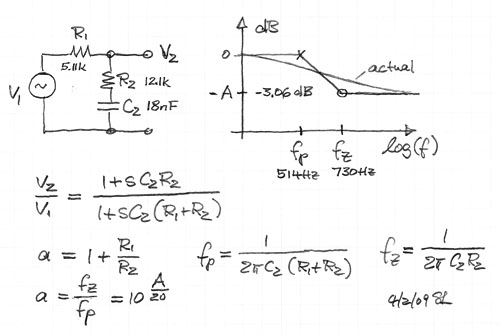 R1 is your gain pot, R2 is the Yogi's 1k5, C2 is the cap I'm proposing, and A (times -1) will be basically your maximum passband gain. |
|
|
|
Post by reTrEaD on Apr 14, 2023 22:59:29 GMT -5
Put a cap in series with that added resistor. It theoretically shouldn’t have DC gain, but in practice probably will. With a cap in series with the ground path of the resistor for the inverting input, the DC gain will be unity. As far as choosing a value, we know if we double the impedance from the inverting input to ground, the gain will be reduced by a factor of roughly two (-6db). It will slope down at a rate of -6dB per octave until we reach unity gain. The 1uF capacitor thetragichero suggested as a starting point would have a 1.5k capacitive reactance at 106Hz, hence -6dB. This is a bit high if all you're looking to do is minimize subsonics. But we're gilding the lily by adding this low-cut. I recommend making the changes suggested by Yogi B first. JMO. |
|
|
|
Post by frets on Apr 14, 2023 23:10:44 GMT -5
Thanks guys for all the help.
Thanks Trag for the corner frequency cutoff calculator; however, I don’t yet know what cutoff I want.
Thanks Ash for your thorough explanation and formulas. I think you have discovered the problem with my gain pot (if I’m reading you right).
|
|
|
|
Post by Yogi B on Apr 14, 2023 23:56:02 GMT -5
I'm pretty sure the location of the 100nF is incorrect, and should instead be between the op-amp's output & the tone stack. Having a cap as necessary series route within the feedback loop would mean there was no DC coupling between the output and inverting input. This means DC would subjected to the open-loop gain of the op-amp (typically in the hundreds of thousands), which definitely wouldn't sound "okay" (either no output or oscillation). I agree completely on your assessment of the mislocated 100nF cap. Regarding how this circuit will act, I think we need to take a closer look. Until a capacitor charges, both ends will be at the same voltage. Since the impedance of the feedback loop is many orders of magnitude lower than the input resistance of the op-amp (10 12 ohms), the gain is essentially unity. I'll admit I got a little confused there. But to be clear, I was considering what would happen once the 1k5 resistor was in place, that'd allow for much faster charging of the cap, but now I've realised the output would only be clamped to the positive supply until the 4.5V rail had come up to above the op-amp's threshold for phase inversion. (Unless Rx went to DC ground via a cap, in which case I think it'd work temporarily, but eventually end up latched.) This is the first time I actually looked at those R values, and 25K over 1K5 is kinda like not much gain hardly at all. Like, less than 20x vs the ~100x in the screamer. Designwise, yep, but I was more focused on troubleshooting with minimal component changes. Trying to keep the gain at a reasonable number in the hope that it should be relatively obvious over the whole rotation of the linear drive pot that something was happening, even if it was only a tame boost. Though, relatedly, the lower V F of germanium diodes should mean less gain is required from them to clip. On the other hand, when they do clip, the softer knee of Ge would work towards keeping the actual distortion modest, even with higher gains — and come to think of it, I don't think I'm aware of any pedal that uses (exclusively, a single pair of) Ge diodes configured for soft clipping, they're commonly doubled up with something else or used as hard clippers. |
|
|
|
Post by frets on Apr 15, 2023 11:29:46 GMT -5
Thanks guys,
I get it now regarding filtering. You know some things go over my head sometimes. Thanks for bearing with me.
BTW - I plan on using D9E’s.
|
|
|
|
Post by unreg on Apr 15, 2023 14:22:00 GMT -5
frets, A really short pinch to zoom video… try this on your iPhone to enlarge Yogi’s image below to read his purple notes. Ignore the finger circling. Use 2 fingers on your phone’s screen to do the pinch zooming. edit: Oh, and to zoom back out: just move two fingers closer together on your screen.
|
|


