|
|
Post by kaustinwright on Dec 5, 2023 14:56:55 GMT -5
Hello again all!
I have what seems to be a simple idea which is proving to be a bit more complicated than I expected. I have a Keisel HH guitar with the below switching:
Position 1: Bridge Humbucker
Position 2: Bridge inside coil split
Position 3: Bridge inside and Neck inside coil split
Position 4: Neck inside coil split
Position 5: Neck Humbucker
I never use Position 2, so would like to have both Humbuckers in series in this position instead. It has a standard Strat 5 way switch, (with which I don't believe my desired wiring is possible) so I purchased a fender 5 way Super Switch.
Can anyone point me in the direction of a wiring diagram with something like this made possible? I am a novice, so have included a quick drawing of the current wiring for reference as it seems Kiesel has used the inside coils rather than screw coils, which is also throwing me off a bit.
|
|
|
|
Post by kaustinwright on Dec 5, 2023 14:58:33 GMT -5
|
|
|
|
Post by newey on Dec 6, 2023 5:35:07 GMT -5
What you want should be possible with the Superswitch. I don't recall a diagram with that specific configuration, so we'll probably have to draw something up. I can do one in the next couple of days, unless someone steps up in the meantime.
|
|
|
|
Post by kaustinwright on Dec 6, 2023 9:15:08 GMT -5
|
|
|
|
Post by reTrEaD on Dec 9, 2023 17:46:57 GMT -5
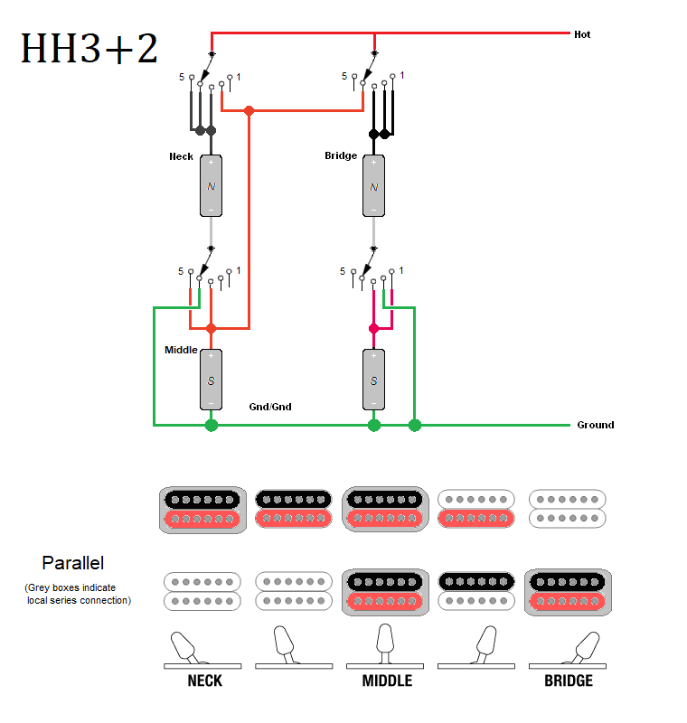
Hi kaustinwright . A while back I created a switching scheme for 2HBs that is similar to what you're asking for. The differences are: - All selections will hum-cancel.
- The position with 2 HBs (local series, combined in parallel) is in the #3 position.
- Position #4 has both of the neck coils in parallel. This provides a bright tone, similar to a HB split to a single coil but it hum-cancels.
- Position #2 has the south coil of the neck and the north coil of the bridge in parallel. This will hum-cancel. IF the neck pickup is rotated such that the north coil is closest to the neck and the south coil is closest to the bridge this selection will be 'inners'.
 If you like this, I reckon newey could use this as a starting point when he creates a wiring diagram for you. |
|
|
|
Post by kaustinwright on Dec 12, 2023 18:20:55 GMT -5
Thanks for the response! It Seems great as a starting point. Of course there are a couple positions that would need to be swapped. I'm a bit of a newbie, so not sure exactly how to read the diagram with the split humbuckers but will sit down to see if I can work it out.
|
|
|
|
Post by newey on Dec 13, 2023 19:34:16 GMT -5
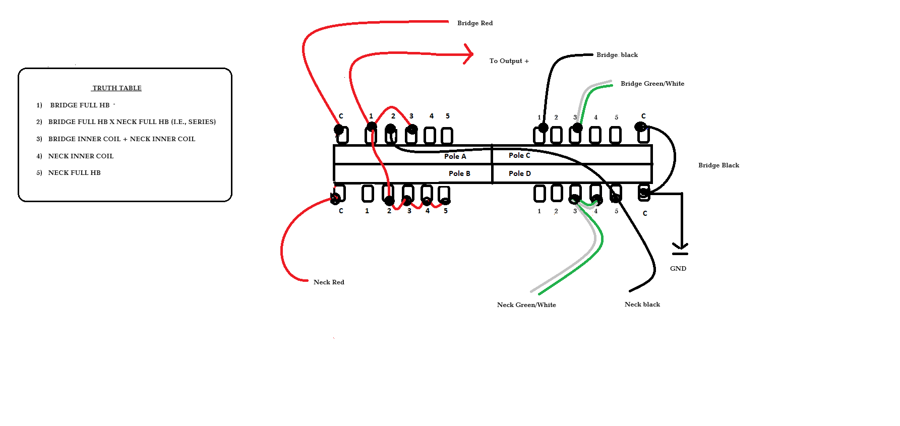
OK, so here's my take on this. I did use reTrEaD's scheme as a starting point but there were so many changes the end result doesn't look much like the original. And, it needs to be vetted before you start wiring. One potential issue. I tried to follow the diagram of the existing wiring so as to get the coil polarities right. I show both HBs wired the same way (with red to the + output, black to ground) as it looked to me as if that was the way it was on your diagram. But I had trouble sussing that out from the diagram, I'm not really following it. I also don't know anything about these pickups as far as whether the neck and bridge are of like polarity for N and S. I assume that with both inner coils selected, it will be one screw coil and one slug coil. This would only be an issue at position 3, where both HBs are split; the question is whether they will be hum-cancelling at that position. If they aren't (and we should be able to figure that out before you start wiring), there will need to be a small change to the diagram at position 3. Also, it may be necessary to rotate one of the HBs 180° to get both inner coils- depending on whether I'm right about the issue above. Also note that I have omitted all the other wiring except for that to the switch; everything else will stay as it is if it's a master V and T setup. If not, let us know.  |
|
|
|
Post by reTrEaD on Dec 14, 2023 1:16:10 GMT -5
I didn't look at every position but the first thing I noticed was: There's no connection to throw 2 on any of the four sections of the superswitch. |
|
|
|
Post by newey on Dec 15, 2023 7:24:56 GMT -5
There's no connection to throw 2 on any of the four sections of the superswitch Yeah, that's an "oops", forgot to add that last wire from my hand-drawn draft to the paint file. Correction coming shortly. |
|
|
|
Post by newey on Dec 15, 2023 7:32:55 GMT -5
Realized I also forgot to label the ground wires and omitted the bridge ground (which is permanenetly grounded but the diagram hardly made that clear.) Hopefully second time is the proverbial charm.  |
|
|
|
Post by reTrEaD on Dec 15, 2023 10:50:14 GMT -5
Hopefully second time is the proverbial charm. I think there's a problem in position 3. (Both North coils in parallel) Neck North (+) red and Bridge North (+) red, connect to the output via the left side poles of the switch. Okay. Series links of both HBs connect to ground via the right side of the switch. Okay. That gets you both North coils in parallel (the specified combination). Neck South (-) is also connected to the output via the orange wire. Not okay. That will place the Neck South, out-of-phase, in parallel with the desired combination.
It took me a few minutes to understand why you would connect the Neck South (-) to the Bridge North (+). Then I realized it's to accomplish ALL FOUR COILS in series, in position 2. That is literally what kaustinwright said in his OP, but we should determine if that's actually what he meant. It will be a challenge to accomplish this and I'm not 100% certain that's what he meant. This will be a high-output combination but it have a very dark tone. If having the two HBs (each with their coils locally in series), in a global parallel combination (like a Les Paul 'both pickups' configuration) is what he desires, that will make solving this problem much easier. If he really does want all four coils in series in position 2, maybe that's possible, but getting there isn't obvious to me. |
|
|
|
Post by reTrEaD on Dec 15, 2023 15:43:35 GMT -5
If he really does want all four coils in series in position 2, maybe that's possible, but getting there isn't obvious to me. After allowing this to swirl around a bit, it became more obvious. I changed the roles of the two poles on the left side of the switch (and the pole on the upper right).  I'm not sure this is the best solution. Doesn't hum-cancel in position 3 and all four coils in position 2 might be a bit dark. But it does accomplish what you ( newey) were going for without the extra coil problem and it doesn't shunt any unused coils. |
|
|
|
Post by kaustinwright on Dec 21, 2023 21:13:12 GMT -5
Thanks so much for the responses. I'll give this a shot and let you know what I find!
|
|
tubejockey
Rookie Solder Flinger

Posts: 24
Likes: 6
|
Post by tubejockey on Jan 4, 2024 0:07:40 GMT -5
Just eliminate the connection from PU2 center tap to SW1 section 3. This gives you all your requested options but with a slightly different order. If you want your stated order, you will need to swap a few connections on section 3 of SW1.  |
|