prozac2502
Rookie Solder Flinger

Posts: 1
Likes: 0
|
Post by prozac2502 on Apr 20, 2024 9:33:56 GMT -5
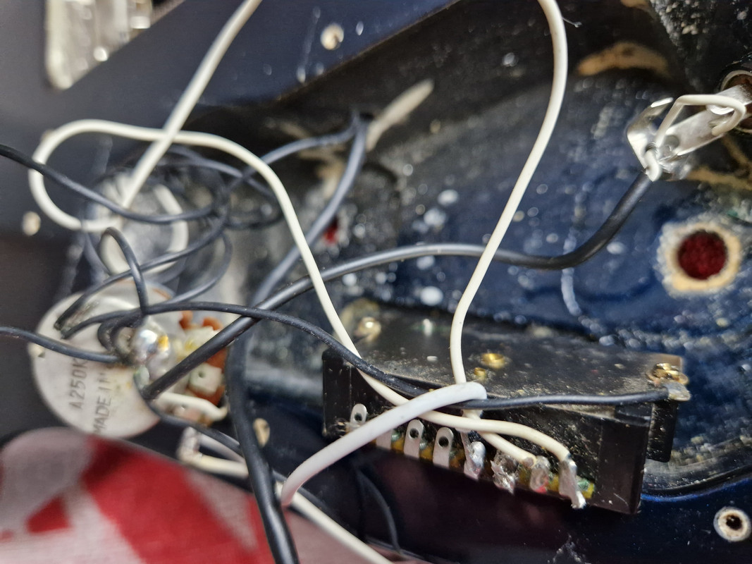
Hi, I have an old Jackson Stealth EX Professional from the early nineties with an HSS configuration (1xvol, 1xtone, 5-way blade). The pickups are 2x Jackson J-110 & Jackson J-75. Something in the electronics broke over a decade ago an I haven't played it since but recently wanted to get it back to working order. I have a Schaller Megaswitch E and new pots and a cap. The plan is to set it up to the HSS4 configuration. I've attached here the diagram for it from Schaller and what I assume is the correct modification for a single tone configuration. The single coils have three wires and based on what I've read the extra wire is a ground for the cover. The colors are one white and two black and the original wiring has the white wire going to the switch, one ground to the back of the volume pot and the other ground going first to a fixed point in the wall of the cavity and from there to a different solder point on the back of the same volume pot where the first ground is. The bridge pickup has 5 wires; green, black, white, red and bare. Black goes to the switch, green and bare to the back of the tone pot and the red and the white are twisted together and terminated. The original wiring is quite messy but I've tried to attach photos from multiple angles. The questions: 1. Is there a purpose for having the two grounds from the single coils take a different path or can the same ground point be used directly for both? 2. Is the modified diagram valid with simply adding the extra ground wires from the single coils? Any other feedback is welcome as well.             |
|
|
|
Post by frets on Apr 21, 2024 17:43:44 GMT -5
It’s always best to follow a diagram 100%. That would mean the humbucker ground runs to the switch.
All other grounds can run to the back of a pot(s), including your single coils.
I’ve done basically this configuration before. It’s a nice configuration.
Anyway, that’s my two cents😺
|
|