|
|
Post by ozrictentacle82 on Apr 25, 2024 21:31:53 GMT -5
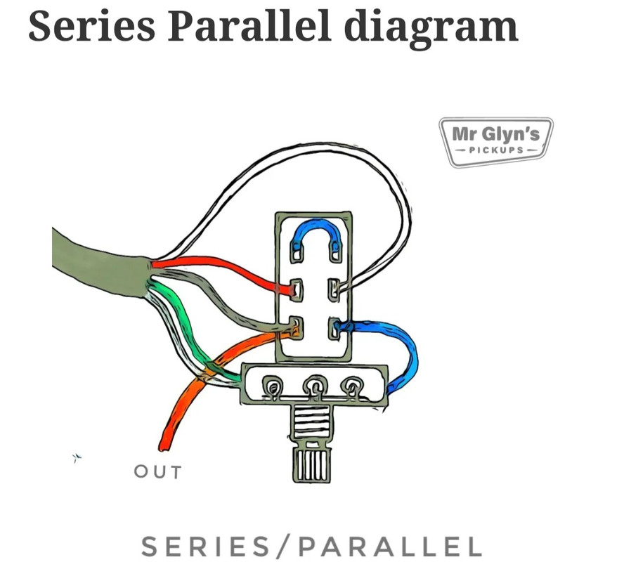
Hello. New forum member, but not new to soldering. I have encountered a problem recently with series/parallel switching, both with on/on/on DP3T switch using the Seymour Duncan wiring module for series/coil/parallel for a humbucker. That was solved by mirroring the diagram, as it was Type 1 vs Type 2 switch. However, I have tried using a DPDT to do only series/parallel for an Artec pickup, and the Green is hot, black is GND, and white and red are same as standard I believe. Here is how it was to be wired:  Seems pretty straight-forward, yet I have working sound on one end and nothing on the other. What gives? What am I missing? Any help appreciated. |
|
|
|
Post by ozrictentacle82 on Apr 25, 2024 22:34:54 GMT -5
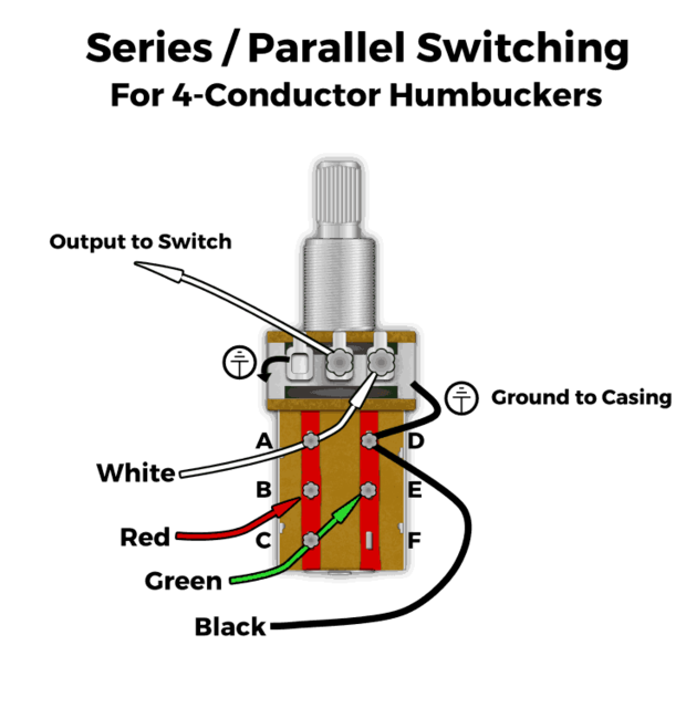
I'm guessing that wiring was not going to work, as it appears to differ from this Lindy Fralin one:  |
|
|
|
Post by newey on Apr 26, 2024 6:06:11 GMT -5
The Fralin diagram uses Fralin wiring colors, where green/red make the series junction, black is grounded and the white is the "hot" output. The Fralin diagram also shows the wiring to the pot, which is being used as a volume control. The first diagram omits the wiring to the pot, presumably because that pot might or might not be used to control that pickup, or might be used for something else. Also, with the first diagram, we have to make the assumption that the blue wire from the lower right lug and the green/bare wire pair are both being grounded to the body of the pot; the diagram implies that, but it is a bit unclear the way it is shown. At any rate, either diagram should work, with the above caveat. Since it isn't working, a bad connection is one possibility. Assuming you've checked the connections and they are good, there are only two other possibilities-either the switch is faulty (fairly unlikely but possible) or the wire colors for the pickup you are using are not what you think. Are you sure it is an Artec? If you are sure it is an Artec, then I think you've got the colors correct. You can also test a pickup to ascertain its wire color scheme by using this technique: www.projectguitar.com/tutorials/electronics/how-to-determine-the-color-code-for-a-humbucker-r35/ But if the manufacturer is known, the manufacturer's information is presumably accurate. |
|
|
|
Post by reTrEaD on Apr 26, 2024 11:13:41 GMT -5
I have tried using a DPDT to do only series/parallel for an Artec pickup, and the Green is hot, black is GND, and white and red are same as standard I believe. Seems pretty straight-forward, yet I have working sound on one end and nothing on the other. What gives? What am I missing? Regarding the first diagram, If you have sound in the series mode and no sound in the parallel mode, I'd suggest swapping the position of the red and white wires on the switch. |
|
|
|
Post by ozrictentacle82 on Apr 26, 2024 13:55:48 GMT -5
Hello. Thanks for your input! I will try swapping the red/white wires.
Just for clarification: I have the DPDT series/parallel and a 3 way toggle running to one volume and tone, no push/pull since guitar it's in is too shallow (some Teisco type guitar I converted from one to two pickups for a friend).
|
|
|
|
Post by stevewf on Apr 26, 2024 16:22:10 GMT -5
... Green is hot, black is GND... As opposed to the drawing, wherein Green is GND and black is hot? If there's a mixup, it could cause the two coils of the humbucker to be out of phase. The resulting sound might be considered "not working." |
|
|
|
Post by ozrictentacle82 on May 1, 2024 13:46:00 GMT -5
... Green is hot, black is GND... As opposed to the drawing, wherein Green is GND and black is hot? If there's a mixup, it could cause the two coils of the humbucker to be out of phase. The resulting sound might be considered "not working." Either way my wires are crossed! 🤪 |
|
|
|
Post by ozrictentacle82 on May 6, 2024 18:30:31 GMT -5
Happy to report that switching the red and white wires did help. I also have got myself into the practice of continuity testing mini toggle switches.
Thanks again for your swift and accurate responses!
|
|