|
|
Post by stevewf on Jun 18, 2024 10:07:50 GMT -5
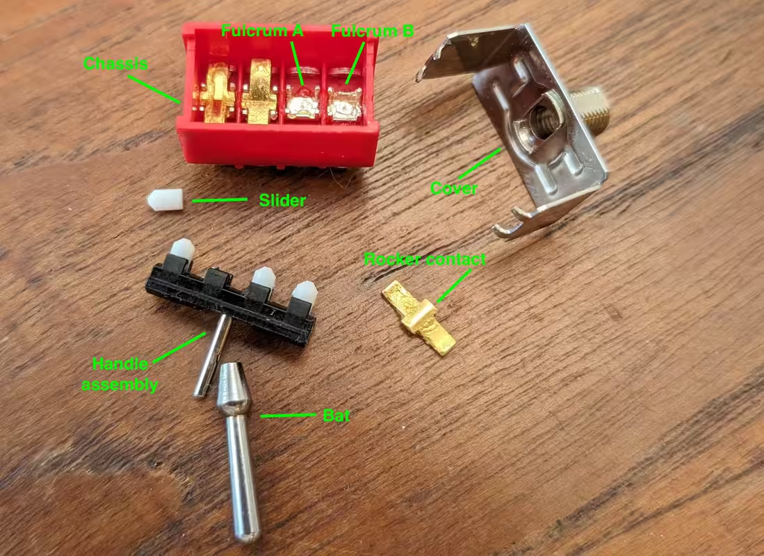
Here's an annotated photo of a 4PDT On-On-On mini toggle that I took apart while investigating opportunities for modification.  (the part names are my own unofficial concoctions) It looks like the shape of the "fulcrum" determines which way the rocker contact will lie when the handle (and slider) is in the middle position. One side of the fulcrum sticks up higher than the other side, which causes a bias in the tilt of the rocker. When the handle is moved off-center, its sliders move outside of the fulcrum's position, overcoming any bias. I also took apart a On-Off-On switch that looked like it was made by the same mfr (sorry, my photos were so poorly focused that I discarded them). The main difference that I noticed was that the fulcrum is symmetrical; both sides are raised. This gives the rocker a non-tilted resting position when the handle/slider is in the middle position. Incidentally, when I tore the switches apart, I was trying to make a 4PDT "Kent Armstrong" combo On-On/Off-On switch, where two of the poles are On-On-On and the other two are On-Off-On. It became clear that I would need to swap fulcrums ("fulcra"?) from one chassis to another, but I was defeated by epoxy. I haven't yet torn apart any On-On switches; if I do, I'll try to remember to update this thread with findings. |
|
|
|
Post by ssstonelover on Jun 18, 2024 13:59:09 GMT -5
stevewf thanks for that image and the explanation. That's a clever way to get the lever to break connection for an end position -- and no spring required, just some fulcrum bias offset between pairs of DPDTs or 4PDTs. It's not really a make-before-break connection as it just prolongs a make over 2 "clicks" before a "break". It just forces a selected connection to stay ON when the lever is fully offset or in the center (to that same selected side). In a sense it could be considered an on-on-off / off-on-on (for each pair of poles and throws) which then makes it on-on-on 'globally speaking'. Here is my fast-and-dirty of what you've brilliantly shown. I'm showing just side "1". Side "2" of any pair would be the same but reversed...that's all. 
|
|
|
|
Post by JohnH on Jun 18, 2024 15:42:23 GMT -5
very interesting to see that. And apart from the on-on-on ones, your sketch shows how these toggles make the connections one way when the lever goes the other way.
|
|
|
|
Post by ssstonelover on Jun 18, 2024 19:29:36 GMT -5
JohnH, a bit crude, but yeah.
|
|
|
|
Post by stevewf on Jun 18, 2024 22:21:40 GMT -5
I'd say that Bethany's hand drawings do show how the switch functions, especially in the close-up of the fulcrum, which shows that one side is higher than the other. She also included some things I didn't even mention. I'll try to offer more detail: - that "fulcrum" is of course also the same piece of metal that forms the center solder lug, the "common" - the two contacts for the outer positions are likewise single pieces of metal that serve also as soldering lugs - the above conductors pass through holes in the chassis, and they're held in place with epoxy, which also seals the unit from dust (and thwarts my modding efforts) - it's the shape of the rocker that provides the detentes; this on-on-on needs poles with opposing fulcra in order to have the detente - the geometry of the fulcrum is aligned relative to its slider's outer position; the slider goes back and forth past the raised part of the fulcrum to switch the rocker; the raised fulcrum is offset from center, but the slider can travel even further outward - I think the chassis is made of ABS and the cover is made of steel; the cover and bushing (not labeled in the photo) are separate metal pieces; probably the bushing is made of something softer than steel - the bat slips on over an internal handle, and it's held in place by the specially-shaped cover; perhaps this enables the mfr to offer a choice of bats for a given switch - I think the slider is made of nylon; not an expert - I lost the fourth rocker before taking the photo; the kitchen floor ate it, despite rigorous searching. Goodbye Mister 4PDT on-on-on  |
|
|
|
Post by stevewf on Jun 18, 2024 22:39:45 GMT -5
Oh, and some notes from memory about the on-off-on switch:
The difference that I noticed was the form of that center contact, the fulcrum. In the on-off-on switch, both sides of the fulcrum were raised.
Otherwise, it was extremely similar to the on-on-on version. The covers were identical to my eye, as were the chassis. Chassises? Even the rockers appeared to be the same.
The modding that I was attempting was to end up with a 4PDT switch with two poles being on-on-on and two poles being on-off-on. If I manage to remove the epoxy, maybe I could swap a pair of fulcra from one switch to the other. Even if I could, there's a risk that the detentes wouldn't work, because I wanted the two on-on-on poles to be in synch (not opposed); there may be insufficient resistive force provided by the on-off-on sections, in the absence of the stronger-looking on-on-on's that got replaced. I had to try, though, y'know?
|
|
|
|
Post by ssstonelover on Jun 20, 2024 3:16:13 GMT -5
stevewf Very valiant indeed, bravo. They sure make it hard to cook up your own variant. Persevering may still result in success, or failure, hard to know that until you go further on the modding (epoxy and cannibalized fulcums) willing.
|
|