|
|
Post by newey on Dec 18, 2007 22:09:21 GMT -5
OK, so I've been posting here and there on this board for the past couple of weeks. But now I have an honest-to-god wiring question. I'm in the middle of a Strat project with a single HB. (Not a real Strat, mind you, but assembled from EBay pieces/parts.) I'm using a GFS dual lipstick-tube bucker, has 4 wire + shield. Originally. this project was all about aesthetics- I liked the clean look of the one pup with just the V control (Plus it will be a white body and pickguard with white headstock and gold hardware). This scheme had the added advantages of being a) butt simple to wire b) a short wiring path to the jack, and c) keeping that look. The tonal goal is a bright, jangly kind of sound. But now, after reading all the great tech stuff from ChrisK, Sumgai, Wolf et al, the switch bug has bit me (Hmmm . . am I running a fever?). So the new semi-formulated plan would add a 5- position rotary switch, using the mate to my gold V knob so it looks like a tone pot. I didn't see any similar schematics on the board, but I did find this: static.zoovy.com/img/guitarelectronics/-/wdu_h5r00_01which I was going to use but eliminating the tone control from the circuit, just having the V pot and the rotary switch. This gives the following on the 5-way: 1) Both coils series (std. HB) 2) single coil N 3) Both coils parallel 4) single coil S 5) Both series OOP My questions are, First, I can't imagine the OOP option being worth anything w/ one pup. Anything else I could do with the other position? I have a spare onboard preamp (9V powered) I was thinking I could use, if pos. 5 could be used to select the preamp. If so, how to ensure the 9V is only connected when the switch is in that spot? Finally, more basically, is the shaft size on the rotary the same as on a pot so's I can get the (set screw) knob to fit? Trusty soldering iron in hand, I await enlightenment . . . |
|
|
|
Post by JohnH on Dec 18, 2007 22:58:47 GMT -5
Hi Newey What you describe is exactly one half of this design: guitarnuts2.proboards45.com/index.cgi?board=schem&action=display&thread=1138768962It is my LPMaximiser, which has two Hbs with 5-way rotary switches, and also includes a preamp. Its true that that series Oop setting is pretty specialist in its application. It does a reasonable impersonation of the 'am transistor radio' intro to 'Wish you were here' Ive since come to the view that a better 5th option is full series Hb, with one coil bypassed by a 0.047 cap. its like a single coil sound with more low end weight and I use it every day on my proper LP. John |
|
|
|
Post by newey on Dec 19, 2007 0:08:28 GMT -5
JohnH-
Thanks much for the tips. Your circuit looks great and I could certainly cut it in half, as you suggest.
But I like your cap suggestion as an alternative for position 5. The active circuit was supposed to go in my telecopy anyway (next project). I 'm thinking the cap option would "de-brighten" this pup a bit, might give an interesting variation.
Your article (can't just call it a post . . .) also suggested eliminating the OOP option entirely, by going with a 3P4T switch instead. That's also an attractive option to me. Cleans up the design a bit and the whole point of this thing was to keep it simple in the first place.
So I'm cogitatin' on all of that.
|
|
|
|
Post by ashcatlt on Dec 19, 2007 2:10:33 GMT -5
I've got these, three in my strat, one in my LP (with chrome tele knobs), and one in a variable impedance buffer pedal (with the 6th tele knob). The shaft diameter on them is listed as 6.35 mm. The one you linked to is listed as 7mm. None of the knobs I had actually fit the switches I've got. Was forced to ream them out with a 1/4" bit to get them on. I'd suggest using something a little bigger than 1/4" for tele or equivalent metal knobs with set-screws as I'm not sure mine will ever come off!  |
|
|
|
Post by newey on Dec 19, 2007 21:14:26 GMT -5
Hey Ashcatlt-
Thanks for the answer on the shaft diameter question. The knobs I'm using are a gold metal bell shaped style but I'm sure the same reaming technique would probably work.
I worry, though. I'm assuming you backed out the set screw a little before reaming the hole. My concern is that the drill bit is likely to put a burr on the inside edge of the set screw hole, thereby preventing the set screw from "setting". But hey, it's only pot metal anyway, so a little brute force with a screwdriver might deal with that.
Knobs are cheap so it's worth a try. I'll post the results once it's done.
|
|
|
|
Post by newey on Dec 31, 2007 22:26:02 GMT -5
Ok- So I decided to go with a 3P4T Rotary switch instead, as JohnH's article suggested as an alternative. Got me a switch to use so I want to double-check my thinking on the wiring. Sorry about the back of napkin sketch of a wiring diagram for this, but I'm both schematically and graphics-software challenged. But here's what I'm planning: 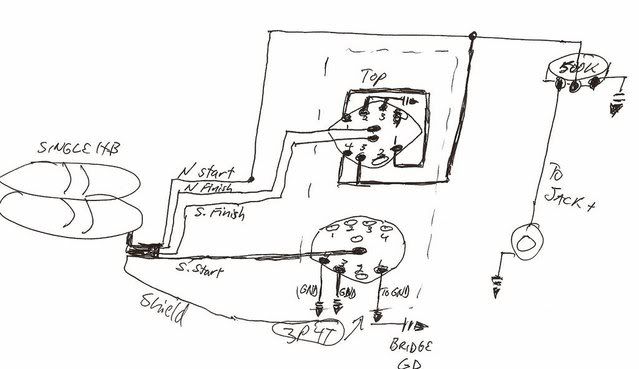 This should give: Pos !- Series HB 2- SC North 3- Parallel "HB" 4- SC South Please let me know my errors before I start dribbling solder all over. |
|
|
|
Post by JohnH on Jan 1, 2008 0:47:24 GMT -5
Hi newey - You have the thinking basically right. Heres a few improvements:
With one volume control, it is better to connect centre vol pot lug to jack, and hot wire from the switch to the left vol pot lug on the diagram, assuming it's viewed from the back
The lower part of the switch as shown, only connects the south start to ground. You can actually ignore that switch pole and wire the south start permanently to ground. Theres no down-side to doing that, unlike having things connected to hot when they are not used.
You draw the switch as if it is two layer. Is that what you have? most 3P4T switches are all on one layer, with three poles in the middle connecting to 3 sets of 4 = 12 outer lugs.
Once you have it going, see what you think of the two single coil options. If you find them to be too similar, or that one is definitely better than the other, a simple rewiring with a couple of changes could give you the "series humbucker with one coil bypassed by a capacitor" sound that I've been keen on recently. I'll call that sound SHWOCBBAC....
John
|
|
|
|
Post by newey on Jan 1, 2008 1:21:45 GMT -5
JohnH-
Thanks for the suggestions, I'll make those changes to the pot wiring and the south ground.
As far as the switch, I stand corrected. What I actually bought from Allparts is described as a "4-position, 4 pole rotary switch" Part No: EP 4371-010. There's no photo on thir website of this but it physically looks like I've drawn it- an upper and lower plate with 4 lugs per side on each plate, plus 2 center lugs for each of the plates.
I don't know if that screws up my diagram or not.
|
|
|
|
Post by newey on Jan 1, 2008 1:42:23 GMT -5
And After Further Review---
The more I think about it, the more I like the the "SHWOCBBAC" option (doesn't exactly roll off the tongue, does it?). What value cap would I need and where would it go in the scheme of things? I assume we're replacing my position 2 (N coil only) with the "Shwoc-back", as I would think if there's only going to be one single coil option it ought to be the coil closest to the bridge.
This sounds a lot like the original Fender Esquire wiring, although that was with a single coil. One of the switch positions gave you a bleed off cap sound on the single coil which was supposed to be the "jazz' setting; at the time, the market for electrics was largely jazz players, and Leo was trying (unsuccessfully) to appeal to them with the cap setting, or so the story goes.
|
|
|
|
Post by JohnH on Jan 1, 2008 3:18:50 GMT -5
If you have a 4P4T switch, then Id expect that to be a two layer unit, just as in your diagram. You still can ignore the lower half on your diagram however, and hard-wire S start to ground. You';ll need to interpret pup wire colours appropriately according to the pup manufacturers code of course.
Its not obvious whether you will prefer the bridge-side coil or the neck side as your single coil option. I think most people go with the one nearer the bridge, but I usually prefer the other one - could be just me.
As to the new SHWOCBAC option (lets see if someone can find the proper name for it - half bypassed?), you just make another series setting which is identical to position 1, with its own separate link joining the two coils (ie not connected to the link that is used in pos 1). Then you put a cap from that link to ground. As to value, I'm finding 39 or 47 nF are most interesting, providing a mid scoop at around 500hZ with humbucker-like bass below and single-coil zing above.
The higher the cap value, the more it tends to the sound of a simple single coil. At about 150nF, you basically have a single coil sound, with just a bit of extra bass from the bypassed coil. YMMV.
John
|
|
|
|
Post by newey on Jan 1, 2008 11:24:57 GMT -5
Ok, so redrawn and neatened up a bit, I get: 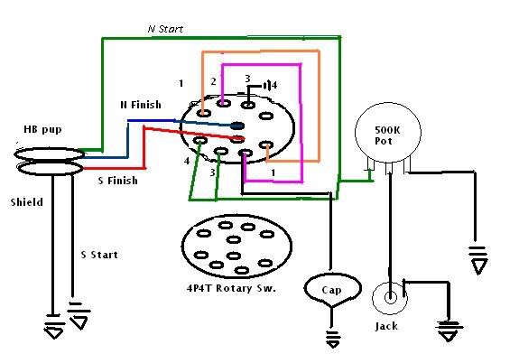 Note that the colors are arbitrary, for contrast. My actual pup is: Black- N Start White- N Finish Green- S Start Red- S Finish As far as a better name than "SHWOCBBAC", since it's bleeding some of the signal to ground thru the cap, I'm opting for "Bloody HB" until someone has a better suggestion. This should give me: Pos 1- Series HB Pos 2- Bloody HB Pos 3- Parallel "HB" Pos 4- SC South Please let me know if I've got this right. And Happy 2008, JohnH, thanks much for the help. |
|
|
|
Post by JohnH on Jan 1, 2008 14:11:44 GMT -5
That would work, but heres a slightly better version:  Lets agree that the south coil is the one you want as the single coil option, as you had it. Also, looking at the colour codes you listed, they look like Seymour Duncan codes? in which case the south coil is the adjustable one (if any). If you have an adjustable coil, its better that that is the main single coil, so you can tweak it. The problem with the previous version (I apologize for not spotting it first time round) is that, with the N coil not used in position 4, it still had one lead connected to the hot. This can act like an antennae to pick up unwanted hum. So I moved the coils around so that the N coil is the grounded one, so this will not happen. The other way to have fixed it would have been to use one of the unused poles, but its better to keep wiring simpler. The other optional addition I added while I was messing with the diagram is treble bleed. When you reduce volume on a guitar, particularly with a 500k pot, the cord to the amp acts like a capacitor and cuts treble at reduced volume. This is because the output impedance of the guitar is much higher when at lower volume, due to the pot resistance. The extra cap and resistor keeps the treble better intact through the volume range. This is definitely not a must-have addition, you might prefer it without since you don't have a tone control, but i thought id add it for reference. Final thought for now - you have all those switch poles spare - If you find you wish you could reduce treble in certain settings, or maybe other tone tweaks, those poles will be useful for adding in separate fixed tone control combinations of capacitors and resistors, chosen for each setting. cheers John |
|
|
|
Post by newey on Jan 1, 2008 15:01:31 GMT -5
John-
The pup i'm using is a GFS "double lipstick tube" type so pole pieces are a non-issue. The only adjustment is the overall pup height.
Am I reading your mod right, there's a jumper between 3 and 4 on the "top half" of the top plate, and no connection to 4 on the "bottom half" of the top ("top" and "bottom" referenced as they appear on the diagram)?
Thanks again.
Paul
|
|
|
|
Post by JohnH on Jan 1, 2008 16:01:12 GMT -5
yes thats right
John
|
|
|
|
Post by newey on Jan 1, 2008 16:37:31 GMT -5
Ok, then, that's the final design. Now, if I wasn't in the midst of a freakin' blizzard here, I could be out getting those caps and wiring today. Guess I'll just have to stay inside and crank up the amp this afternoon instead.
|
|
|
|
Post by newey on Jan 6, 2008 22:12:30 GMT -5
Well, I finally got this wired up this weekend, ready to go into the guitar. But I've got some clearance issues with the rotary switch in the cavity so some woodworking is in order now. I'll post it when it's all done.
Meanwhile a big +1 to JohnH for getting me squared away on this.
|
|
|
|
Post by newey on Feb 3, 2008 22:46:50 GMT -5
Well, I finally got the cavity routed out to accept the rotary switch, had to redo all the shielding in that part of the cavity.
The issue was, I put the rotary switch below the volume knob, 'cause I wanted to keep the Strat "pinkie on the volume" technique available. That's one of the things I really like about the Strat design.
If I had switched the rotary into the spot where the vol would normally go I wouldn't have had any problem. But putting the rotary below the vol meant it's in the narrower part of the cavity, so some reworking was required.
It fits, but it's pretty close, so I'm going to put a layer of electrical tape over the shielding in that end of the cavity to ensure that one of the lugs on the switch doesn't make contact with the shielding there.
Other than that, it's ready for final assembly. Still waiting for the tuners to arrive, though.
|
|
|
|
Post by newey on Mar 16, 2008 15:34:48 GMT -5
I'm revisiting this post because I finally got this all done, buttoned up and strung, just needs a bit of set-up work. But I have a problem with the electronics. First, the output of the pickup is very low, sounds good but very little output. Second, my 4-position rotary switch seems to have 6 detented positions! I know it's a 4-way switch from the # of lugs, but it "clicks" six times. And every one of those positions sounds exactly the same, I get signal in all positions but no variation in tone whatsoever. Well, at least there's no hum . . .  Is it possible that I have somehow "stripped" the switch? So it's back to the workbench . . . |
|
|
|
Post by sumgai on Mar 16, 2008 18:38:41 GMT -5
newey, 6-way rotary switch:Perhaps the wafer (holding the terminal lugs) was not meant to be mounted to that particular frame (holding the detent mechanism), meaning it's a factory screw-up? I've never had one in my hands, but I do know that they make configurable multi-position rotary switches. Theoretically, the user can select the number of positions by adjusting a detent block, or some such thing.....  Might you have one of these? The knob is slipping on the shaft?  Same tone in all switch positions: Same tone in all switch positions: and Low output:(combined) Sounds to me like either there's a short across two of the switch terminals (Did you insulate the shielding on the cavity wall with electrician's tape?), or the pickup itself has a major problem. Whether or not that problem was created by you remains to be seen.  HTH sumgai |
|
|
|
Post by newey on Mar 16, 2008 19:37:55 GMT -5
Easily checked. No, same result with the knob off. Not as far as I know, I got it from Allparts hereYes. Clearly, this needs to come apart so I can check for a short, but I'm thinking that a 4 position switch with 6 positions is not going to be useful, so probably looking at a new switch and redoing the whole shebang. I also used John H's treble bleed on the Vol, as per the diagram above. If I got a wrong value cap and/or resistor, could that account for the low output? I thought I was being extra-careful at Radio Shack but I'd never bought a capacitor or resistor before. So maybe I screwed that up? |
|
|
|
Post by ChrisK on Mar 16, 2008 23:34:44 GMT -5
Well, did you buy a 0.001 uF (1nF) film cap and a 220,000 Ohm (220K) resistor? You have to be careful since some folks in the rest of the world make up goofy units like nano Farads. So, you get output in all 6 positions? Sounds like a job for digital multi-meter man. Set the volume pot to full on. Measure the DC resistance at the output jack for each of the 6 positions. Write the values down (in actual Ohms or Kohms) to at least 3 digits of accuracy. Post these values, including the resistance of each of the pickup's coils and the volume pot (you DID measure and record these before you started, didn't you?). Obvious will be. |
|
|
|
Post by newey on Mar 17, 2008 5:48:34 GMT -5
Thanks, Chris- Yes, and since it's really only a 4 pos. switch, that must mean that the switch is shorted right out of the circuit altogether and is doing nothing. But I'll meter it and post the results. Actually, er . . .ah . . . well, I . . .no.  |
|
|
|
Post by pete12345 on Mar 17, 2008 11:33:04 GMT -5
Just a suggestion, but now you're using only 2 poles of a 4way switch, you could try using the special fender 4way blade switch (intended for teles but still fits) That would be more in keeping with the strat look.
Pete
|
|
|
|
Post by newey on Mar 17, 2008 19:19:19 GMT -5
Pete- Thanks for the suggestion but I already put the hole in the pickguard for the rotary, so I'm pretty much stuck with that. Actually, it looks very nice with matching knobs, looks just like V and T controls, but the tone knob is actually a rotary switch. But of course, none of that matters if'n it don't work right . . So I did as Chris suggested and introduced it to the meter. And, yes, we have a problem. As I suspected the reading is exactly the same in all 6 switch positions, but it's an incomprehensible 1.00 M&Omega! So, I checked my phone jack/microclip test rig- no resistance there. I next put the meter to my recently-wired (and working fine) Esq-type and got a much more reasonable 9.45K &Omega (Bridge HB in series). I then went back and checked the suspect in question, same reading. I then varied the Vol pot from full on down to full off, and got steadily decreasing readings, about .700M &Omega, then .630M, .380M, etc, down to 0.00 at full off. Now, I'm guessing that Chris is gonna berate me for not getting the readings on the pup in advance, as well as the pot, but I'm thinking it doesn't really matter. It looks to me like I'm gonna hafta undress the new girl. (Honest, Hon, I mean the guitar . . .) |
|
servant
Meter Reader 1st Class

Posts: 64 
Likes: 0
|
Post by servant on Mar 17, 2008 23:20:04 GMT -5
newey,
While you've got it apart, why not go back to basics and just wire the pickup to the volume pot like you originally thought, or straight to the jack? That was you can test the output level with the meter, and the tone of the pickup with your ears. Then you can introduce the 4 position (or was it 6?) switch and go from there.
servant
|
|
|
|
Post by ChrisK on Mar 19, 2008 19:17:24 GMT -5
And while you're at it, take some pics.
500Kvalue is the volume pot If it's 1 M Ohm that you're reading there's a problem. What overrange value does the meter indicate when the leads are not connected?
While you're in there, measure the resistance of each coil.
|
|
|
|
Post by newey on Mar 19, 2008 20:11:48 GMT -5
Thanks, Chris- Haven't unbuttoned her yet but will post pix once I do. ( Always had trouble with that one-handed brastrap move anyway  ) Meanwhile, I'm working on setting it up, etc. But I wanted to have a better idea of what's wrong (if that's possible) before the strip- down. My meter is autoranging (w/ manual range selection as well). Overrange, according to the manual, is indicated by a blinking 3rd sig. digit, which I've never seen. With both leads disconnected, in any range selected, the display reads ".0L", which is normally the "too low" range indicator- I assume that's just a default setting. Resistance has 6 ranges, from 400&Omega to 40M&Omega Two other points: On a recheck today, I got a measurement that varied between 1.003 and 1.001M&Omega, still the same in all switch positions, but before I was getting 1.000M consistently. Also, there is a remote chance that I might have put a 1M pot in there by mistake- although I KNOW I double-checked it- Would that account for this? I'll have to look in the parts drawer to see if I still have that 1 Meg pot around- if it's disappeared, must be in the git! |
|
|
|
Post by sumgai on Mar 19, 2008 21:28:17 GMT -5
newey, "OL" means "open loop" - the circuit, or loop, is open. On a resistance range, it means that you're out of bounds, for a moment, until the auto-ranger can settle down. If the third digit blinks when reading a resistance, I'd be real suspicious of the meter itself. (But that's probably OK for a voltage or current reading.) If you're reading 1MΩ (your postings read "Omega" because you aren't ending with a semi-colon!), that's great...... except........... does twisting the volume pot affect this reading? If not, you live in Houston, 'cause you got a problem! And you have one anyway, because out of the guitar's jack, you should never read more than the DC resistance of one or more of the coils. Either the pot is bad, or you soldered the square peg into the round hole........  HTH sumgai |
|
|
|
Post by newey on Mar 19, 2008 21:57:52 GMT -5
Sumgai- Thanks for chiming in on this. First, I'm seeing the Greek symbol, not sure what you are referring to . . Yes, in the manner I described in my second-to-last post above. I don't understand that statement. I thought that the pot (even when wide open) and the wires, switching, etc. would add some resistance to the circuit (although, granted, not anywhere near the readings I'm getting here.) Highly likely. My thought is, however, that I probably have 2 independent problems here. Clearly, the rotary switch has to be replaced, since it doesn't have the 4 positions it's wired for, and it seems to be out of the circuit altogether as no variation when using it. But could that also explain the low output? The sound is full, doesn't sound like I wired the coils out of phase, but with my amp on 10 it sounds like it would sound at about 2 with any of my other axes. Of course, I don't know what the pickup is supposed to sound like when it's correct, so maybe the coils are just reversed. |
|
|
|
Post by sumgai on Mar 20, 2008 2:46:42 GMT -5
newey, Sorry, I must have missed the volume control action, as you twist the knob, the resistance does indeed change as expected. My boo-boo.  But nonetheless, every pickup coil has a DC resistance factor, it can't be avoided. That DC resistance component is in parallel with the tone control, and effectively in series with the volume control - when the pot is not at full volume (10 on most guitars). When the pot is at full up, the pickup coil is in parallel with the pot... Q.E.D. This means that if we apply some basic arithmetic regarding how resistors behave in various combinations, we'll see that when two resistors (or to be more precise, when two resistance elements) are in parallel, the total resistance seen across the two devices cannot be more than either individual resistance. Obviously, if a coil has a DC resistance of, say, 8KΩ, then it doesn't matter what the volume pot's resistance is, the maximum you could possibly read at the output jack is a tiny fraction less than 8kΩ, period. Since you're getting the resistance of the pot itself, it's obvious that either the pickup is bad, or it's mis-wired somehow - it certainly is not in parallel with the pot, or if it is, then it's busted, with a capital 'B'. Which would explain the very low output, and possibly the same tonality in all switch positions. Exploratory surgery is indicated. ~!~!~!~!~!~!~!~ On my screen, for the last couple of weeks that you've been posting ohms (using the ampersand-O-m-e-g-a-semi-colon regimen, which should come out as the Ω symbol,), I've been seeing only the amperand and the word 'Omega'. That happens only if there's no closing semi-colon. If your browser is rendering the character as written, then it's making up for a coding mistake. Not necessarily a bad thing, but it's embarassing to be caught out writing code for a shortcut browser, and to not follow the standard (all character codes begin with an ampersand, and end with a semi-colon).  Just for drill, let me request that you double check for the semi-colon before posting your next message..... then we'll see if I find the Ω character, or if it's still the text string. As things stand now, if I do a "quote message" when I go to write this, the quoted text from your message shows no closing semi-colon. Quote this message to reply to the thread, and you'll see what I mean. And thanks. sumgai |
|


 Might you have one of these?


 ) Meanwhile, I'm working on setting it up, etc. But I wanted to have a better idea of what's wrong (if that's possible) before the strip- down.

