|
|
Post by mr_sooty on Mar 30, 2008 21:56:24 GMT -5
I was just wiring up a pre printed, solder ready PCB for an effects pedal kit, when one of the little silver circle things you solder to came off. What can I do? I've lost the circle thing, it's tiny. How can I save my pedal? The solder obviously won't stick to the board without the little circle thing!
|
|
|
|
Post by wolf on Mar 31, 2008 0:22:48 GMT -5
Okay, nothing like a diagram right?  Let's suppose that point B is the "silver circle thing" that fell off. One solution is to connect a wire on the other side of the board from A to B. ORIf you want to stay on the printed circuit side of the board, somewhere along the line from A to B, you'll probably be able to solder a wire. connect the other end of the wire to point B. You really don't have to have the "circle thing" on the board and instead you can use the other end of the wire to wrap tightly around the component lead at point B. |
|
|
|
Post by D2o on Mar 31, 2008 9:14:44 GMT -5
Great idea, Wolf.
In the past, when I have done similar sounding projects with these boards, "jumpers" were often called for.
In other words, if you need to create electrical continuity between one "circle thing" and another, you would take a bit of the lead for a capacitor or a resistor and crimp and solder it from the one specific "circle thing" to the other specific "circle thing" required to complete whatever connection is called for.
|
|
|
|
Post by mr_sooty on Mar 31, 2008 14:59:03 GMT -5
Cool, so if the pad fell off at point 'b', could I just leave the leg of the diode unclipped, and if it reaches, pull it through the hole at point 'b', then just solder it to point 'a'? That's where the signal's going anyway right?
The guy from the websit I got the kit from told me to scrape back the board along the trace line with an 'exacto knife' to expose the track, and solder directly to that. But I would think it'd be easier just to solder directly to the next point along (a) right?
|
|
|
|
Post by sumgai on Mar 31, 2008 16:18:07 GMT -5
sooty, Both Dan and wolf have it correct (so +1 for both of 'em!). In wolf's image, you're seeing an idealized situation - it's ideal for explanatory purposes that the pad (that there circular thingie) at Point B is at the outer end of the board, and easy to get to. Ditto for Point A, it's easy to see and get to. In most cases however, Mr. Murphy (who's on newey's payroll, but he's also a well-known midnight freelancer!!  ) will dictate that you have boogered a pad in the middle of the board, and that the next pad in line, electrical-circuit-wise, will be at the far end, after wrapping around several other connections. Soldering a component's long lead (stuck through the hole) to that distant pad is perilous to the circuit's health - mucho opportunity for short circuits and such.  So, like the support person said, you need only scrape back a bit of masking insulation from the trace that runs up to the pad, thus exposing some copper. Now you can bend the lead over to fit that exposed portion, clip it short to fit, solder it down, and you're done. Not much chance of causing unexpected shorts, eh?  For future reference....... that pad pulled up and away due to excessive heat. If all the pads and traces pulled up, I'd say there was a manufacturing defect, but only one pad? Too much heat, me bucko, pure and simple. The only known cure for that is practice, practice and more practice.  HTH sumgai |
|
|
|
Post by mr_sooty on Mar 31, 2008 18:27:49 GMT -5
Yeah, I know it was too much heat. It happened because I accidently got some solder in the hole before I put the component in, and I had some trouble getting the solder out of the way.
The good news is that 'point A' is as accesible as the one in wolf's diagram, so it shouldn't be a problem getting the leg of the diode across to it. So if that's gonna work I'll try that before I start with the scrapey scrapey.
|
|
|
|
Post by wolf on Apr 1, 2008 0:28:45 GMT -5
sumgai
Thanks for the +1 Karma Point.
I had a feeling that diagrams always make discussions so much easier.
|
|
|
|
Post by mr_sooty on Apr 1, 2008 1:22:30 GMT -5
Well that went alright. All looks pretty good, no idea if it's actually gonna work or not, but we'll soon see!
|
|
|
|
Post by D2o on Apr 1, 2008 9:17:04 GMT -5
Well that went alright. All looks pretty good, no idea if it's actually gonna work or not, but we'll soon see! Thanks for the vote of confidence, sumgai. Mr. Sooty, good judgement is the result of experience. You are going to find, as time goes by, that your experience will make you a better and better resource and source of good judgement around here. +1 |
|
|
|
Post by mr_sooty on Apr 1, 2008 14:48:15 GMT -5
Well that went alright. All looks pretty good, no idea if it's actually gonna work or not, but we'll soon see! Thanks for the vote of confidence, sumgai. Mr. Sooty, good judgement is the result of experience. You are going to find, as time goes by, that your experience will make you a better and better resource and source of good judgement around here. +1 I hope so! As you can probably tell I'm actually pretty clueless about electronics. I'm just good with my hands so I get you guys to tell me what to do and I can do it. I've done quite a few successful mods thanks to this site, and I get a real kick out of it! Hopefully I can finish the pedal today, and hopefully it works, because I will struggle to find the fault if it doesn't. I have a multi-meter, but I don't reall know how to use it! I love this stuff though, it's fun. Maybe I'll go take an electronics course one day and get a clue. |
|
|
|
Post by D2o on Apr 2, 2008 9:18:43 GMT -5
I hope so! As you can probably tell I'm actually pretty clueless about electronics. I'm just good with my hands so I get you guys to tell me what to do and I can do it. I've done quite a few successful mods thanks to this site, and I get a real kick out of it! Hopefully I can finish the pedal today, and hopefully it works, because I will struggle to find the fault if it doesn't. I have a multi-meter, but I don't reall know how to use it! I love this stuff though, it's fun. Maybe I'll go take an electronics course one day and get a clue. When I first came to this forum, I knew nothing and actually came here in search of help when I accidentally detached a wire in my first electric guitar. Man, am I glad that I found this place! Funny thing is, a lot of people on this forum came here the same way. As you go along, reading things and trying things ... and screwing up things, you learn. When I said good judgement is the result of experience, I didn't want to complete that and risk offending you by saying "and experience is the result of poor judgement". But I think you are okay with that. So keep on tinkering, enjoy the screwups, learn from your mistakes, and teach others from them. Regarding, your multimeter, if you have not read ChrisK's tutorial, I highly recommend you do so: guitarnuts2.proboards45.com/index.cgi?board=reference&action=display&thread=1176413665This is with respect to measuring the output of your guitar, as opposed to pedals or anything, but it will still teach you how to use the meter. I suspect that whatever project you are working on at a given time would also supply information on the desired readings, which you can attain in more or less the same manner. I have taken the following from another post as well, to summarize the physical steps involved in getting the measurements: - connect the probes to the “COM” and the “Volt/Ohms” or “Volt/Ohms/mA” inputs - set your multimeter to it's highest setting, to protect it, but in practical terms you will set it to 20k ohms - touch the tips of the probes together and you should see a "0" on the display. - plug one end of your cord into your guitar. - connect either one of the probes to the tip of the loose end of the guitar cord, and connect the other probe to the sleeve of the guitar cord. - with the volume control at minimum, you should have a reading of "0". - next, with the volume at maximum, you should have a higher reading – it could be up to 15000 ohms (in which case your display would say "15.00"). - then set the meter to 2000k ohms. - with the probes still attached, rotate the volume knob and record the highest level of resistance (it should be 125 – 250, depending on your pot) – it should occur somewhere near the middle volume. |
|
|
|
Post by ChrisK on Apr 2, 2008 11:30:02 GMT -5
This is a good one too. Discerning Paralleled Resistances One only needs to select the highest range when connecting a meter to an unknown voltage or current (a goes_inta, (gee, I hope that it's less than the maximum range on my meter)). Resistance measurements are a goes_outta from the perspective of the meter. However, don't connect it to a voltage or current when in resistance mode............I don't know what range is best for that.  One might suggest the precautionary measurement for a possible voltage prior to measuring resistance. (And no, you can't be strumming the strings while measuring resistance.) There are often questions as to what range a meter actually is on if auto-ranging. In the manual, and on the selector knob, will be the ranges. There will be a decimal point displayed for any given range (or not displayed if there is no decimal part of the range). The displayed decimal, in conjunction with the overall maximum range of the meter tells one explicitly what the range, and hence value is. .xxxx x.xxx xx.xx xxx.x xxxx Where xxxx is 0 to 1999 (3 1/2 digits) I recommend a 0 to 3999 meter (3 3/4 digits) or better. Many meters have a range hold button that helps (don't forget to turn it off when you need a different range. The best way is to turn the meter off and back on. |
|
|
|
Post by mr_sooty on Apr 3, 2008 3:40:29 GMT -5
OK, so I finished putting the pedal together, and well, surprise surprise, it doesn't work. The light switches on and off via the footswitch, which is a good thing. I just get no sound. It's a true bypass design, so I would have thought that if the problem was in the PCB, I would get sound with the pedal off. Another interesting point is that there's a pop from the amp when I turn it off, suggesting there is signal of some sort going to the amp. All the wires seem to be in the right place, as far as I can see.
So, where do I start trying to figure out the problem. Any ideas? There's so many things it could be that I just don't know where to start!
|
|
|
|
Post by RJB on Apr 3, 2008 13:58:32 GMT -5
If the pop is when the effect is disengaged with bypass. Then my guess is that there is a short at the input. Between the input and the bypass switch. The pop is caused by the shorted input being switched from the effect pcb input to the being directly across the amp input.
If this device is intended to have power turned on by inserting a plug into the input, like most commercial pedals. I would look for tip and ring being swapped at the input jack.
RJB
|
|
|
|
Post by sumgai on Apr 3, 2008 14:54:38 GMT -5
sooty, RJB beat me to it! My first thought is 'reversed power polarity' - check it out. sumgai |
|
|
|
Post by mr_sooty on Apr 3, 2008 15:38:10 GMT -5
I'm 99% sure the jacks are wired the right way around, I checked and double checked before I did it, but I'll check again.
|
|
|
|
Post by mr_sooty on Apr 3, 2008 17:08:47 GMT -5
I'm wondering if there might be a mistake in the istructions. They have included a wiring diagram, and a photo, but they don't look the same. Here's the wiring diagram: www.generalguitargadgets.com/pdf/ggg_mbb_lo.pdfand here's the photo (scroll down): www.generalguitargadgets.com/pdf/ggg_mbb_instruct.pdfWhat I'm wondering about relates to the black wires on the input jack. In the wiring diagram there are three black wires connected to the sleeve, but I can only see two in the photo. Also, there seems to be two black wires connected to the output sleeve in the photo, when the diagram shows only one. I know there is supposed to be a non-true-bypass wiring scheme for this pedal too, but the switch wiring is the same on the photo as it is in the diagram. Anybody wanna play 'spot the difference'? |
|
|
|
Post by mr_sooty on Apr 3, 2008 17:24:20 GMT -5
|
|
|
|
Post by ChrisK on Apr 3, 2008 18:38:03 GMT -5
|
|
|
|
Post by mr_sooty on Apr 3, 2008 20:11:04 GMT -5
Oh...my....God.....  Chris K, how do you do that? Are you psychic? You have come to my rescue yet again. You are truly my hero. I want to marry you but I'm hetrosexual and have a wife unfortunately. So you just take a wild stab in the dark that I may have made a completely basic and embarrasingly obvious mistake like that, and you hit the proverbial nail right on the proverbial head. Switch turned and re-wired, pedal fuctions perfectly. The only thing wrong with it is the tell-tail unproffesional nest of wires on the inside that scream 'first time pedal builder'. But it sounds just like it should. Here it is: 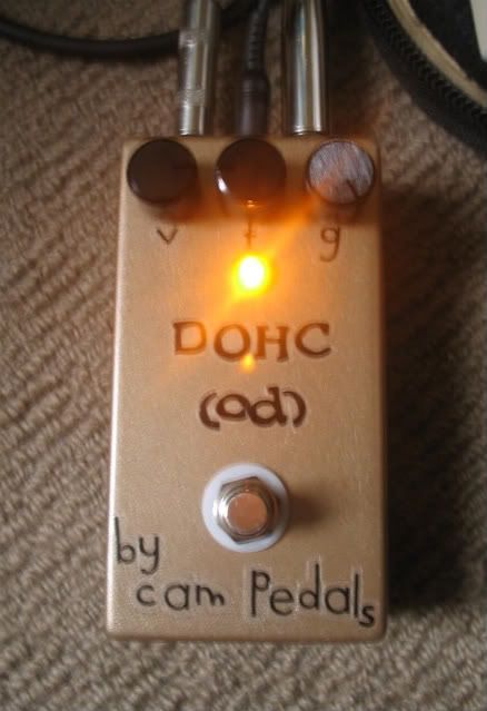 My name is Cam, Dohc as in Double Overhead Cam. It's a Marshall Bluesbreaker (original black version) clone, a very cool bluesy overdrive. Nice to have made my first pedal. Thanks so much for your help! Genius is. |
|
|
|
Post by wolf on Apr 3, 2008 23:46:59 GMT -5
Congrats mr_sooty and of course ChrisK.
|
|
|
|
Post by mr_sooty on Apr 4, 2008 14:46:12 GMT -5
Congrats mr_sooty and of course ChrisK. Thanks for your help with the PCB part too Wolf. That worked a treat. |
|
|
|
Post by ChrisK on Apr 4, 2008 15:59:20 GMT -5
I submit the following post in only the most humble and honest intent. Unfortunately, I was born with, and suffer from AFB (riddle in). No wild stabbing involved, what happened was patently obvious to me (detail is). I have found substantially rewarding employment over the decades exactly because I see things, in ways obvious to me, that few other humans do or can. One gots to mind their syntax. Because, "a wife , unfortunately" indicates that you have a problem. But, "a wife unfortunately" indicates that she does.................. |
|
|
|
Post by mr_sooty on Apr 4, 2008 16:16:39 GMT -5
What is AFB? |
|
|
|
Post by sumgai on Apr 4, 2008 18:16:28 GMT -5
sooty, Ah, ah, ah! Does Macy's tell Gimble's?  Well, if a clue is deserved........ what kind of brain would you suspect Chris of having? Big Hint: It'll never be full! HTH sumgai |
|


 ) will dictate that you have boogered a pad in the middle of the board, and that the next pad in line, electrical-circuit-wise, will be at the far end, after wrapping around several other connections. Soldering a component's long lead (stuck through the hole) to that distant pad is perilous to the circuit's health - mucho opportunity for short circuits and such.


