|
|
Post by TooManyWires on Dec 31, 2007 15:00:42 GMT -5
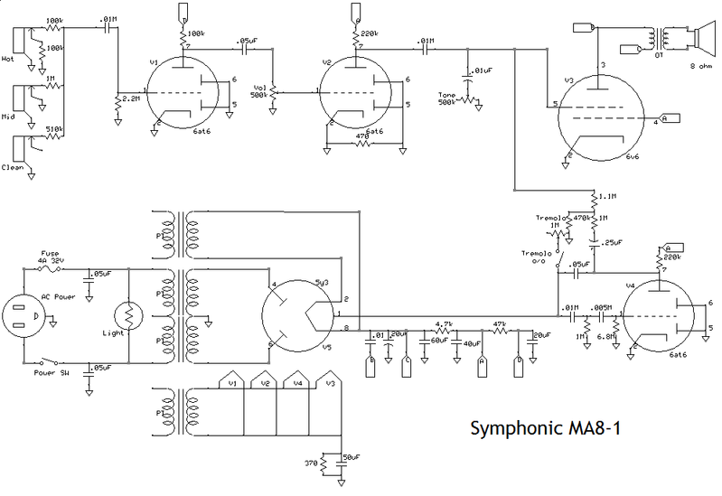
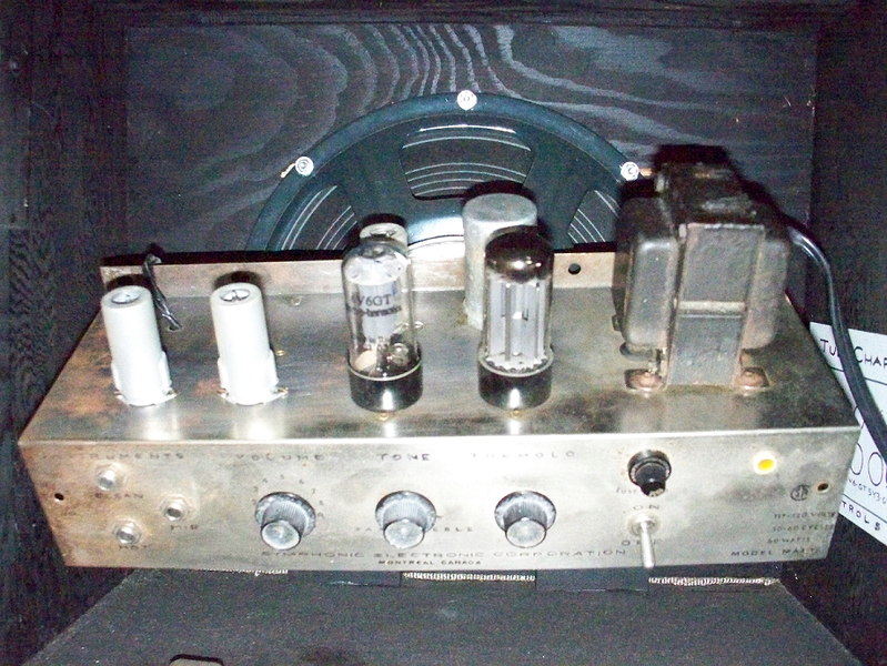
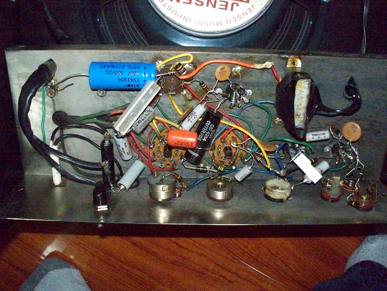
I've got an old tube amp that hasn't worked right for a very long time, that I'm trying to troubleshoot. The most unfortunate thing about it is that I don't happen to have a patch cord around this place to test it with, so I'm sort of working from memory on what was broken about it. As I recall, when it was turned on and warmed up, it would sound like the notes were coming through, but breaking up and sort of cutting in and out in a really harsh clipping sort of way when they started to reach full volume. Hard to describe, especially without a patch cord to test it out again. I think I'll have it somewhere with a little more test equipment around the end of the week sometime maybe. Here's a schematic of it:  I've checked all the resistors to see if they're all good, and there were two blown up ones, the 1M on the middle input reads at around 200k and the 470 across the grounds of the second 6at6 reads open. (Which I'm not sure I follow as to why that would be there anyway...) So I wouldn't expect either of those to have caused any really fatal sound problems all the time. The only real diagnostic tool I have is a multimeter, so I'm not really sure how to check and see if the capacitors are still good. There's a few capacitors marked with .01M or .005M, and I'm not sure what that exactly means, because .01MF would be a ridiculously high amount,maybe it's supposed to mean M for micro, they're ceramic caps, so I'm not really sure how to interpret them. However, from the reading I've done capacitors would be a good place to start from on an older amp, should I just replace all of those right from the start? And what should I do about the can cap? Can you get those still, or should I just use caps with the same values that are printed on it? The other thing is, that this amp has had some work done on it at some points in the past, so something may be hooked up wrong. And I took it to a tech person once and he told me that he thought the output transformer wasn't right. He figured it was way too small. I'm also not really sure on how to check a transformer to see if it's good or not. And if I can get it back up and running, I'd like to add a standby switch. Where would I do that? On the ground tap of the rectifier part of the power transformer? Oh, and to make things all the more fun, it's wired point to point, so here's a couple of pictures just to show what it looks like on the inside:   |
|
|
|
Post by sumgai on Dec 31, 2007 21:13:07 GMT -5
TMW, Only been a "few" months since last we saw you 'round these parts, right?   Patch cord? What patch cord? Do you mean a regular guitar cord? Whaddya mean, you don't have one on hand? How do you play guitar? Anyways?  ;D My first suspicion would be either the 0.05µf or the 0.01µf capacitors coming off the plates of the 6AT6 preamp and driver tubes. If DC gets past those, then the grid of the following tube is way under-biased, and the resultant signal out is swamped. Yes, the 'M' designator is 'micro', so the value is 0.000,001 times whatever or 10 -6. I too am also puzzled by the "extra" 470Ω unit between ground and ground, on the driver tube. Seems to me that this might be a holdover from another design, and the proofreader didn't catch it before publication. And the error has remained ever since.  BTW, your "blown" 1MΩ resistor is actually being shunted by the pair of 100KΩ resistors (in series) that are connected to the jack above your suspect.  Always disconnect at least one end of any component you are checking with a multimeter, or you may get unexpected/incorrect results.  The best simple standby method is indeed to interrupt the high-voltage secondary center-tap. There most certainly has been some previous work done here. See that blue 20µf/500VDC cap in the upper left of the chassis? That's a replacement for one of the sections of the multi-section cap (in the can), the one you already suspect might be bad. Do the same thing, replace the rest of the sections with caps like the blue one, but of the appropriate value, of course. You can't hurt the re-sale/collector value any more than what's already been done, unless you go to extraordinary lengths to procure and install period-correct parts and pieces. The worth of doing that kind of restoration is up to you. I wouldn't worry about the output transformer, the 6V6 is so under-powered, I doubt it could work up enough sweat to blow out a candle, let alone any transformer larger than a baby's fist. Speaking of which, see the two callouts on the primary of that transformer? From what I can tell, it looks like one comes from point "C" (on the power supply), and the other from point "B". That can't work, I don't care what engineering school that guy attended - the two points are effectively the same, on the diagram. Again, I suspect rather strongly that an editorial error (of a large magnitude) has been made. My guess about the speaker? The cone looks too good, like it's not very old, or else it was kept in a "clean room", absolutely dust-free. Is there a date code on that thing? Last but not least........ I can see you're from way up north - nice socks, eh! ;D sumgai |
|
|
|
Post by TooManyWires on Jan 1, 2008 0:12:28 GMT -5
Yeah, it's been a while since I've been around, I seem to fall in and out of the habit. Good to be back though. As for the patch cord thing, I live in another province 8 months of the year, and I keep all my equipment there, save this amp and one guitar which I keep here for occasions like this. I knew this amp was blown and I'm perfectly content to go unplugged for a few weeks, but seeing as I'm studying electrical engineering, curiosity got the better of me on this one and I couldn't resist taking a look at it. Thanks for the tip on those resistors, that's probably what I'll start out with. As for the speaker, truth is, I've had this amp for a couple years, in various stages of working, none of them ever very good. When I bought it, it only had a crappy old 8" stock speaker in it, so I picked up a 12" replacement of the same impedance online and stuck that in there to try to help the tone. So, that pretty much kills any resale/collector value right there, since I cut a big hole in the front of it. I also replaced the fabric covering the front and painted the whole wooden chassis, so yeah, that doesn't really matter in the slightest. That schematic is one that I drew up from the amp itself. I've looked all over the internet everywhere and I can't find anything at all about this brand of amp, so it is quite possible that I made mistakes in it. I'll take another look at it, and see if I can see any mistakes I have in it. I also at one point replaced the 3 6at6 tube sockets with sockets that have those spring loaded metal jackets to hold the tubes in place. When I did that I was super careful to put things back where they belonged, but it is also possible that I made some kind of mistake there as well. And a Happy New Year from "way up north"  ;D |
|
gpw
Rookie Solder Flinger

Posts: 8
Likes: 0
|
Post by gpw on May 10, 2008 6:44:09 GMT -5
TMW... check out www.sewatt.com for amp repair consultations ...nice guys , very helpful.. ;D ( Edited by sumgai to make the website name a link.) |
|