|
|
Post by sephiroth29 on May 11, 2008 21:51:50 GMT -5
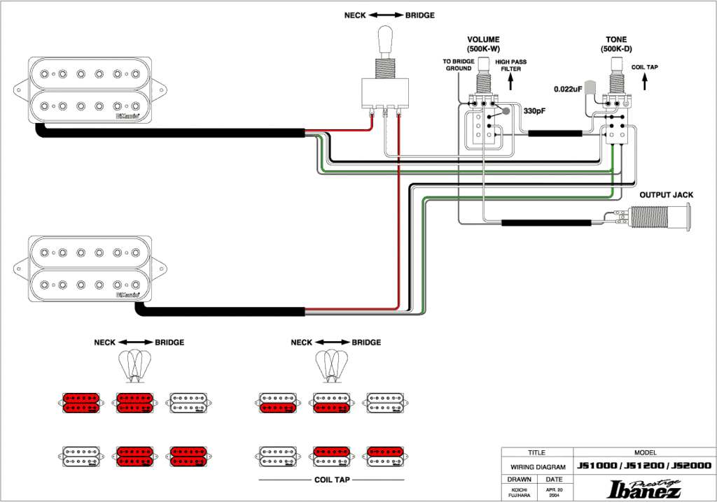
Hey Everybody, First time poster here. Trying to decipher this ibanez wiring diagram.  (2004 Ibanez JS1000 wiring diagram) Now i have read in various places that ibanez's diagrams are sometimes incorrect. Just wondering how this capacitor on the tone knob is connected. Is it connected to the casing and the two poles, or just the end pole on the right. Thanks guys ps. how the heck do i insert an image on this thing!?!?  ( Edited by sumgai to make the link an image.) |
|
|
|
Post by cynical1 on May 11, 2008 22:21:08 GMT -5
|
|
|
|
Post by sephiroth29 on May 11, 2008 22:54:40 GMT -5
Thanks Cynical, ;D This is for a late 90's ibanez with H-s-h setup. The humbuckers (Mo'joe & PAF Joe) will (hopefully) be set up exactly like the js1200 in the above diagram. Also the single coil (Dimarzio YJM) will be on a mini toggle spst on/off switch with it's own vol. and tone knob. This should give it a nice variety of tones to choose from. I play lots of hendrix, satriani, floyd, and other old stuff most people never listen to now.  Hope u guys can help me sort this stuff out. Thanks in advance. |
|
|
|
Post by cynical1 on May 11, 2008 23:55:56 GMT -5
sephiroth29 - According to the diagram, the .022uf cap is soldered to the left lug, and then to the casing of the tone pot. This is pretty standard. There are other options, see the Quieting the Beast page for information on shielding, star grounding, etc.. Another option to consider for wiring the tone control is Wolf's 2 Capacitor Tone Control from this board's own very talented and generous Mr. Wolf. I have this on both guitars in process and on my bass. This is a very simple and slick little modification. I'm certain the rest of the more electronically savvy here will chime in. Happy Trails Cynical1 |
|
|
|
Post by ChrisK on May 12, 2008 19:47:05 GMT -5
The cap needs to be soldered to the casing of the push pull switch (where it completes the tone control circuit's connection to ground) and to both the left and right lugs on the push pull switch (where it functions as the connection jumper to ground for both of the center taps from each pickup for the coil shorting/shunting single coil mode.
Since it's a short across each bypassed coil, it's not a coil tap, but a coil short (no worries aboot damage, just drained energy).
|
|
|
|
Post by sephiroth29 on May 12, 2008 21:03:38 GMT -5
Thanks Guys! U've been a great help! Hope the rest of this project goes off with out a hitch. ;D
Sephiroth29
|
|