Oky
Rookie Solder Flinger
 dogs make the best producers...
Posts: 12
Likes: 0
|
Post by Oky on May 21, 2008 4:39:11 GMT -5
Hi all, this is my first post. (btw I have good hands on skills but not so good elect theory knowledge) Let me say thanks for the wealth of information here. Well Done! I am about to rewire my Ibanez AR250 (LP copy basically) I am going to use a 4P6T rotary switch for pup selection and a push/pull for coil tap on the bridge. I am using a seymour Duncan (bridge) SH-6? i think its called.. 4 wire + bare And a Gibson '57 classic 1 wire plus braid. My questions are: If the guitar cavity is properly sheilded why is it so important to ground the pot bodys? (if using star grounding). Shouldn't the cavity sheilding be sufficient? (this ones just out of interest) using the 4P6T sw there will obviously be many connections with small wire on the sw. If these are made properly (with proper cavity sheilding) would this produce any noticible noise? When wiring two humbuckers in series does it make any difference which pup is closer to output in terms of sound? I was thinking of the following options: 1. Neck only 2. N&B Series "a" 3. N&B Paralell in phase 4. N&B Paralell out of phase 5. N&B Series "b" 6. Bridge only If sequence in a series alters the tone I would make series "a" and "b" opposite sequences as im not that keen on out of phase sounds overall. However if it makes little to no difference I will throw one out of phase to make for a more interesting selection. I will have each pup on individual vol pot, then -> pup selection, -> output. Hope this is clearer than mud.  thankyou in advance for your time. If anyone has any queries comments or suggestions to improve this planned setup they are most welcome. Cheers! |
|
|
|
Post by newey on May 21, 2008 5:11:45 GMT -5
Oky-
Hello and Welcome!
Before finalizing your plans, you may want to search this site on the topic of parallel out-of-phase combinations, as it is a much-discussed issue. The consensus of opinion is that series out of phase is a much more usable tone than parallel out of phase.
AFAIK, the order in which the two pickups are wired in series will make no difference in the sound.
If you don't really want out-of-phase sounds there are other tonal options, such as using a capacitor or two to vary the tone.
|
|
Oky
Rookie Solder Flinger
dogs make the best producers...
Posts: 12
Likes: 0
|
Post by Oky on May 21, 2008 6:14:51 GMT -5
thanks newey, I will look into these options.... can anyone describe the difference different capacitors might make? can they be used in a different way to caps on the tone control? thanks again
|
|
|
|
Post by D2o on May 21, 2008 12:58:09 GMT -5
thanks newey, I will look into these options.... can anyone describe the difference different capacitors might make? can they be used in a different way to caps on the tone control? thanks again thanks newey, I will look into these options.... can anyone describe the difference different capacitors might make? can they be used in a different way to caps on the tone control? thanks again Do you mean cap values? Lower values allow more treble through (0.022 would be bright, and used in single coil pickup like in a Stratocastor) Higher values allow less treble through (0.047 would be a little darker, and used in dual coil (Humbuckers) like in a Les Paul) I guess you could experiment with different cap values to get the tone you want - but they would be "wired in" the same way, if that's what you mean. I hope that helps. |
|
|
|
Post by ChrisK on May 21, 2008 17:15:49 GMT -5
While the shielding does surround the cavity, it should not be depended on for signal continuity. It should have a connection to the back of the main volume pot, which could be the star grounding point. The pot back shells are used since a number of wires can be attached there.
Generally speaking, for shielding with good conduction, it's probably not an issue. However, the connection to the shield thru the threaded bushings on the pots is a mechanical connection and not a gas-tight connection like a solder joint.
A pickup or a series string of pickups forms a two terminal network. Generally speaking, the order of the components does not matter if polarization is not an issue.
As a result, I don't think that your series "a" and "b" are of use.
That being said, there are some limitations that you must follow. Since the Neck pickup is a single conductor plus shield (the other wire), it cannot be split, and also must be the normal polarity ground-referenced pickup in any series chain. It must also be the ground-referenced normal phase pickup in any parallel structure.
In other words, it's the "bottom" pickup.
I would recommend the following combinations in any order that you desire:
1. Neck only
2. N&B Series
3. N&B Series out of phase
4. N&B Parallel in phase
5. N&B Parallel out of phase
6. Bridge only
Note that while N&B Parallel out of phase is weak and very thin sounding, adding a series capacitor of about 0.01 uF to the neck pickup when in parallel with the Out-Of-Phase bridge pickup will help.
Since you are using only an internal series structure for the bridge pickup, the 4 poles on the rotary switch will be sufficient. I would recommend that each tone circuit be wired directly across the respective pickup, with no connections elsewhere on the bridge pickup such as the pot back shell.
Using a volume pot on each pickup in a series structure will be problematic unless the pot is switched from the normal 3 terminal structure when in parallel to a 2 terminal shunting-only structure when in series. While this may seem complicated, it is not.
So, you would have the above structure/combinations and the following control operation.
A. A pickup alone - the volume works as before, the tone works as before
B. Two pickups in parallel, in phase - the volumes works as before, the tones works as before
C. Two pickups in parallel, OOP - the volumes works as before, the tones works as before, the neck pickup output signal goes thru a 0.01 uF cap to the selector switch
D. Two pickups in series - each volume shunts across each coil, each tone shunts/bypasses each coil. This allows much better control over the OOP effect.
Based on my statements, what do you think?
|
|
Oky
Rookie Solder Flinger
dogs make the best producers...
Posts: 12
Likes: 0
|
Post by Oky on May 23, 2008 4:42:30 GMT -5
Thanks very much everyone for your input so far, and answering my questions so clearly and promptly. It is most appreciated!!! (wow a forum where everyone isn't just here to mock and argue!!  ;D) Chris, I think this sounds like a plan.; thanks in particular for this little peice of info: Which is one of the (many) things about gat wiring i didn't know. BTW, What is the "OOP" effect? I'm lost there.... Heres some other things I thought I had covered but now I think I should mention them so that anyone might review them and correct me if i'm wrong... I do want to tap the S/D bridge with a push/pull vol. I wasn't going to use any tone controls- I've had these p/ups in this gat before, first stock wiring, then i wired it: p/ups->select/sw-> output because the pots crapped out. (Boring eh?) truth is I loved the three basic choices. But now I'm going to try to 'broaden my horizons', i think i'll wire a tone onto the bridge, as it can be a bit shrill sometimes. Is 500k ok for this or not?I can only use one tone as I am removing one to install the 6way/sw. I don't want to drill holes. (the 3 way always bugged me as it's up near the top cut away and so is real easy to bump when playing, so this will be left unwired) anyways, here is a schematic(ish?) drawing of what i'm planning; (please forgive my ineptness at using the highly sophisticated circuit design program MS"paint") . Plus I don't know how to draw switches... Chris, or any one else who might be so kind, if you can let me know wether this is correct or not? the main things I'm unsure of are: * Am i using the right coil/polarity with the tap? * Is the tone control correct? * Is the cap in the right place on 'P/Lll out of Ph' ? * Anything else I've done wrong??? 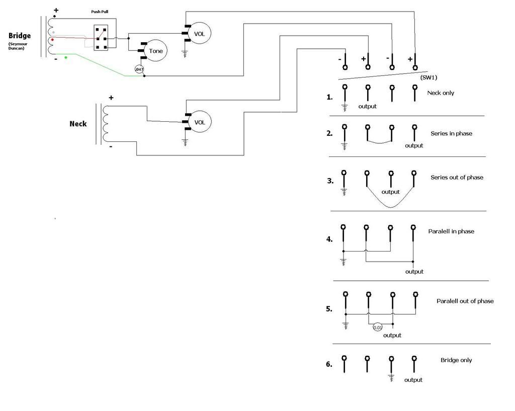 (BTW - earth on the 'out' side of the sw = jack ring (duh)) Thanks very very much to everyone for their time !!! Suggestions most welcome... |
|
|
|
Post by newey on May 23, 2008 5:58:04 GMT -5
OKY-
I can't vouch for your diagram, I'll leave that to the experts here. But a couple of things.
Out Of Phase.
500K should be fine for your tone pot. May we assume the Vol pots are likewise 500K?
One of the things ChrisK mentioned was:
This needs to be attended to, your diagram does not do so.
As far as mockery goes, we have to get to know you better first. ;D
|
|
Oky
Rookie Solder Flinger
dogs make the best producers...
Posts: 12
Likes: 0
|
Post by Oky on May 23, 2008 6:35:35 GMT -5
Thanks newey, good points. yes all pots 500k. Yes the problem... I don't get it. can anyone direct me to a thread/source/diagram explaining this wiring method and how to acheive it? What will happen when selecting a series combo if i don't do it? Cheers |
|
|
|
Post by ChrisK on May 23, 2008 19:56:39 GMT -5
Oh, I didn't look at your parking space.  I see that you need to be OZtracized!  BTW, I have good electrical theory but often can't find my hands..... Out Of Phase as in Serial Out Of Phase (SOOP) and Parallel Out Of Phase (POOP). One is much preferred in a warm bowl over the other. I won't argue this. Why don't you grab it during a sustained power chord, madly wank it aboot, and let the audience try to figure out what just didn't happen? After all, it's not what I wouldn't do. If you scroll down to the Series_Parallel Blend Pot w/ DPDT switch section, you'll see that, on the lower coil, the volume pot is used in a three terminal mode for parallel (the left circuit) and a two terminal mode for series (the right circuit). Two of the volume pot connections in parallel are reversed (pickup to wiper, output from "10" terminal) to avoid one volume pot set to "0" affecting all pickups selected (this normally isn't a problem for the partially sentient., but it also easily lets one go a'shunting in series). (And, you anticipated series modes....) Unless you want the volume pots to weirdly affect both pickups in series, you want to connect their "0" terminal (as in turned all the way down to - information is) to the downward most circuit point for that respective pickup (which also explains what, in equestrian (or at least mule team) terms, "upward" (as in output ho!) and "downward" (as in ground ho!) means). Mild observations and undeservedly rude comments on your, ahem, schematic:1. The schemata-wire-a-tic is actually very good (ok, what's the catch). 2. You have difficulty spelling "parallel", but one of the L's may shift position under negative gravity. 3. Since the neck pickup (-)/shield wire is switched to ground except when the output isn't switched anywhere, it is superfluous and should just be soldered to ground (unless your an advocate of this theory and then should be offended by that person that I quoted). This frees up a switch pole for other uses. You'll need it. 4. I'm thinkin', I'm thinkin'.  OK, You've come to this board prepared with a functional knowledge of how things work, and have therefore minimized our chances to inflate our egos. A clever sort might question the advice given. 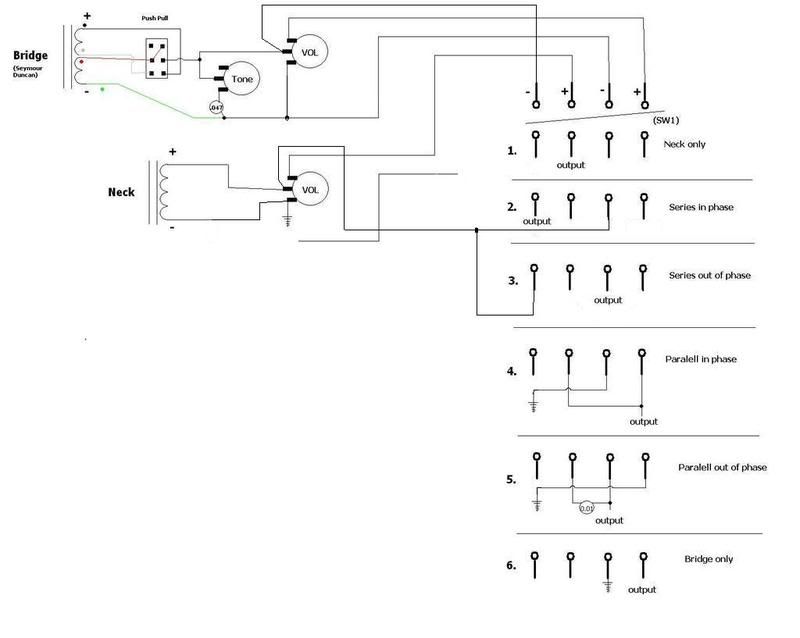 +2 fer the understanding, -1 for the switch. |
|
Oky
Rookie Solder Flinger
dogs make the best producers...
Posts: 12
Likes: 0
|
Post by Oky on May 23, 2008 23:01:17 GMT -5
ChrisK, LMAO!!!! ;D It seems that you are as adept at wordplay as you are at debugging circuits!..... I see that you have used these skills to both ridicule me and correct my diagram.... I thank you. When I stop laughing i'll try to separate the comedy from the theory lesson and see if I can comprehend HOW and WHY it will now work... For now I'm glad to know it will work!!! Oh swt, a spell check button! this will hide my inability to spell disappear, parallel, and any other word with the same letter twice! (pressing button) Phew... And for the record, I'm actually an ex-pat Kiwi, although some how I doubt this will serve to limit the extent of my "OZtracization" ! Oh well, can't be any worse than it is here in aussie...!  BTW, I was thinking of putting the toggle in the output path and disconnecting one terminal ah la Tom Morello, jerking it around then would certainly have some audience members scratching their heads!!! Thanks guys... thanks heaps! If anyone's interested ill post some sound files when i'm done... (still waiting for some parts from your side of the pacific)... till then I can start planning what to do to my strat........ |
|
|
|
Post by newey on May 23, 2008 23:22:22 GMT -5
And, as such, able to take your mocking like a man.  When I'm not playing in the basement, I'm scheming in the attic. ;D Got your wordplay right here . . .! EDIT- No link intended in above. |
|
|
|
Post by ChrisK on May 23, 2008 23:26:19 GMT -5
?Where?(Linky no worky.)
|
|
Oky
Rookie Solder Flinger
dogs make the best producers...
Posts: 12
Likes: 0
|
Post by Oky on May 23, 2008 23:26:50 GMT -5
Heyyyyyyy... I get it!I must say, complicated it may not be, but cunning and ingenious it most surely is! never would have worked that out on my own... This is great for future reference. What threw me off is that the top left connection on the switch "common" side is now on the + side of the pickup, not - as I marked it. 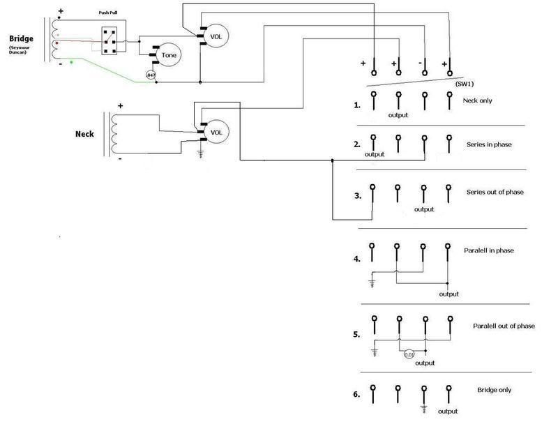 very clever.... very clever indeed (at least in my mind!) Would this be worth posting somewhere as a mod for a LP/LP copy which doesn't alter cosmetics? anyone? |
|
|
|
Post by ChrisK on May 23, 2008 23:30:17 GMT -5
Have at it.
|
|
|
|
Post by ashcatlt on May 25, 2008 0:41:44 GMT -5
I take it the rotary doesn't fit in place of the 3-way? The DP5T fits in there on my Gibson, but it doesn't have any of the terminals sticking out the sides.
Seems to me like a scary place to put a kill switch. Bumping a standard LP switch can be annoying when it goes from one pickup to another. Could be disastrous when the thing just turns off. 'Specially if you've had a couple and you're really thrashing away and don't imediately realize why everything went quiet!
|
|
Oky
Rookie Solder Flinger
dogs make the best producers...
Posts: 12
Likes: 0
|
Post by Oky on May 25, 2008 2:19:12 GMT -5
I doubt it will fit, aside from the fact I think it would look really queer. Im still waiting on the switch in the mail. Yeh I was just joking about making it a kill switch ;D;- it was annoying enough when I kept on changing pickups by accident! 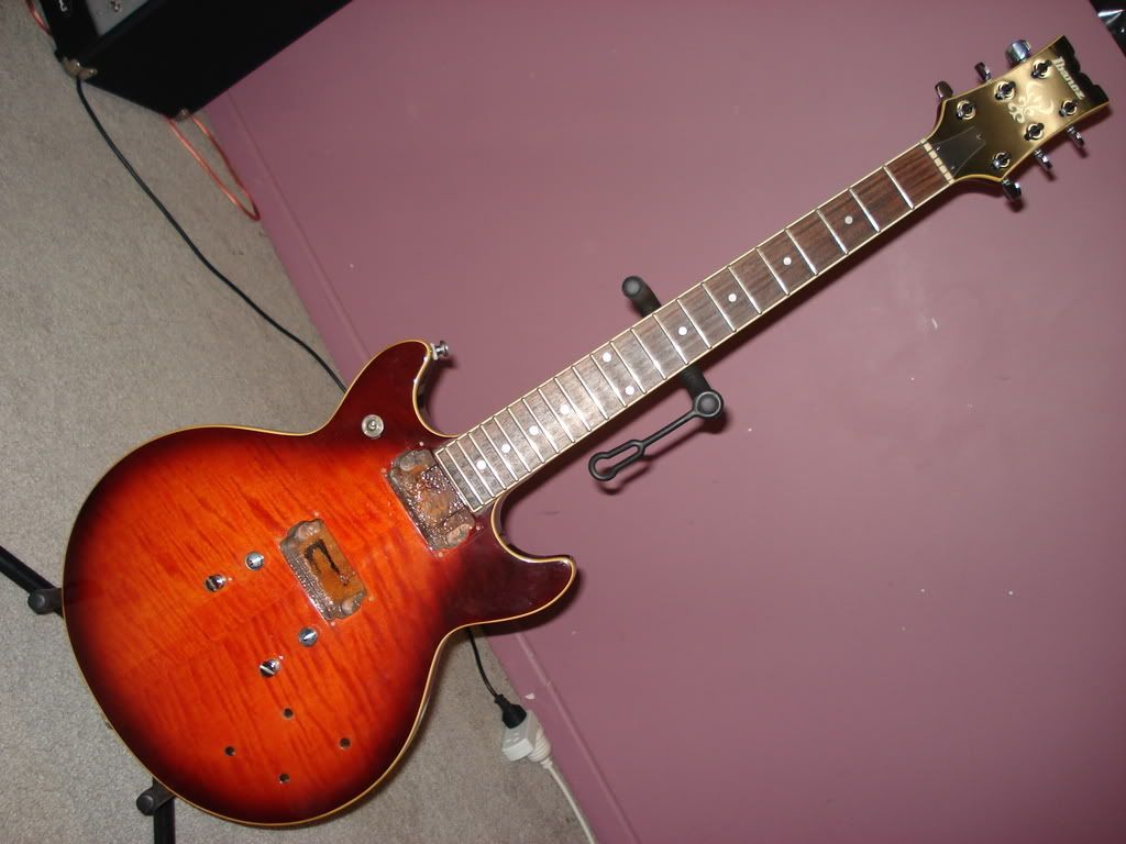 Imagine a big fat speed knob right above the neck pup! ugly? Although maybe it would be nice to have a more symmetrical setup with a tone circuit on both pups.... I'll think about it............ Thanks for the input. |
|


 ;D)
;D)


