hazysonic
Rookie Solder Flinger

Posts: 13
Likes: 0
|
Post by hazysonic on Nov 6, 2008 5:30:15 GMT -5
The idea is to use a single 5-way superswitch and add a 8PDT switch to toggle between normal operation and the most important (IMHO) super sounds that are missing. My diagram is below--feedback is welcome and wanted. I'm put this out there before I attempted a build, since I'm somewhat new to this stuff and want to make sure I didn't miss a shorted connection or something... I plan to still add in a phase reverse for the neck PU, and a mini-switch for my bridge humucker to select serial/parallel/single. The sounds: NORMAL: B, B+M, M, M+N, N SUPER: B*M, B*(M+N), B*N, B+M+N, B*N 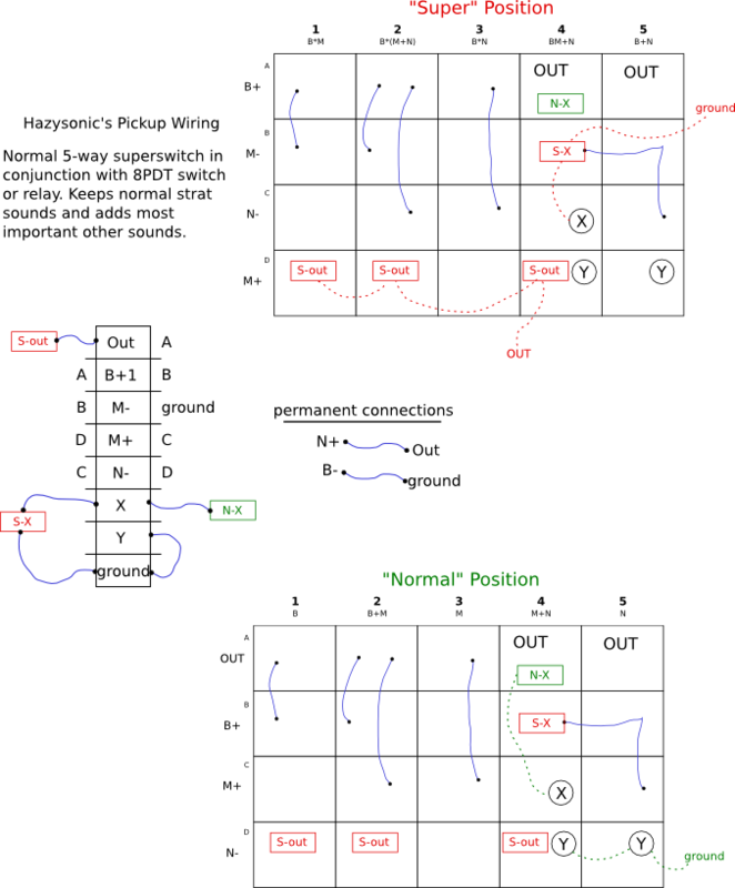 Also, the obvious difficulty is the 8PDT switch. Any suggestions? At this point I'm considering a relay or maybe physically joining two 4PDT switches. |
|
|
|
Post by newey on Nov 6, 2008 6:45:37 GMT -5
Hazysonic-
Hello and Welcome!
Sorry, but I had to move your post here, since it is not (yet) a completed schematic, and you still have some questions about it.
Someone will be along with more info for you shortly.
|
|
|
|
Post by ChrisK on Nov 6, 2008 13:33:29 GMT -5
tedfixxI presume that you meant; NORMAL: B, B+M, M, M+N, N SUPER: B*M, B*(M+N), B*N, B+M+N, M*N Your desired combinations are nearly identical to a Mike Richardson design of yesteryear. It does the following: NORMAL: B, B+M, M, M+N, N SUPER: B+M+N, B*M, B*(M+N), M*N, B*M*N It might be fairly simple to modify the B*M*N into a B*N, you'll have to look at it. I don't want to disappoint you, but it only requires a 4P5T super switch and a 2PDT.  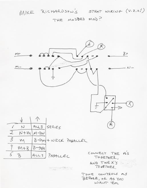 This was his original version, 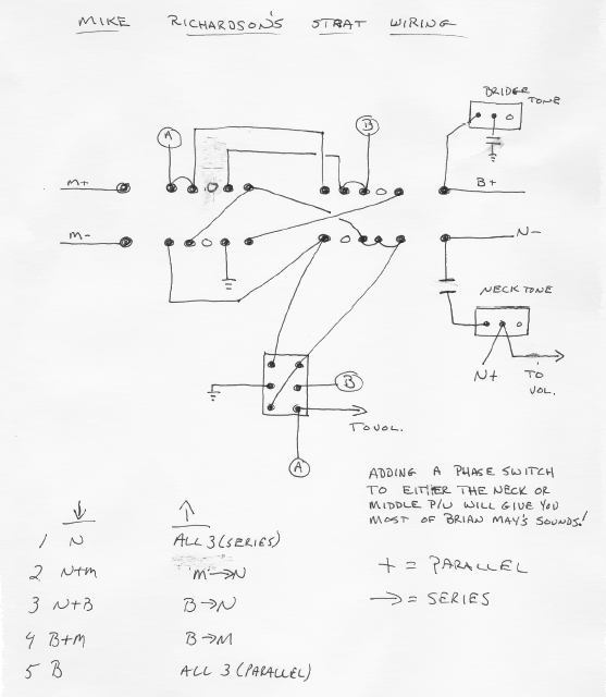 and my implementation of it, Mike Richardson wiring with phasein here. The Padouk Caster
|
|
hazysonic
Rookie Solder Flinger

Posts: 13
Likes: 0
|
Post by hazysonic on Nov 6, 2008 23:12:14 GMT -5
nice guitar build....
yes i looked at that circuit but it misses out on B*(M+N) and B+N, and it has M*N and B*M*N which I don't want. I can't figure out any possible way to modify it without losing stock sounds, which I also want to keep.
I made an error in saying "B*N" for position 5. It should be "B+N", as shown in the actual diagram.
I'll look at his diagram again to see if it can be modified. So far I either haven't found a way or it is beyond my ability....
|
|
hazysonic
Rookie Solder Flinger

Posts: 13
Likes: 0
|
Post by hazysonic on Nov 7, 2008 12:18:15 GMT -5
i just noticed that the mike richards circuit also loses the M pu by itself in normal mode, and I like that sound a lot for certain rhythm parts.
|
|
|
|
Post by newey on Nov 7, 2008 13:00:07 GMT -5
Hazy-
MR's original scheme has B+N at position 3, and B*N at 3 with the switch up. ChrisK's mod of MR's idea substitutes the "M only" at that position, and adds B*(M+N) with the switch up at position 3.
ChrisK's revision therefore has everything you want except B+N. Easiest way to get that (that I can think of) would be a simple on/off for the middle pup.
|
|
|
|
Post by JohnH on Nov 7, 2008 23:08:12 GMT -5
hazy - could you contemplate swapping the positions of B*N and M*B in your 'super' set? (all the rest being as you intended) If so, then a 4P5T superswitch and a 3PDT toggle seems to do what you would wish.  Sketch shows it in normal mode, from 1 to 5: B, B+M, M, M+N, N In 'Super' mode: B*N, B*(N+M), B*M, B+M+N, B+N John |
|
|
|
Post by ChrisK on Nov 8, 2008 0:32:07 GMT -5
Please keep in mind that the order that you want things in may adversely affect the ease of how you may actually have things realized. pathLet's start with the same pole assignment on the 4P5T lever switch. We have four poles; we'll assign one to Bhot ( Bnot is locally grounded), one to Mhot, one to Mnot, and one to Nnot ( Nhot is connected to the output). With this structure, we can trivially do any parallel combination since we determine where each of these four leads go (in a simple one dimensional parallel structure the choices are no connect, and either output or signal common. Let me make it clear that I am not calling anything "ground" since no lead coming from a pickup is EVER a ground except for a shield connection which needs to be locally grounded. These are AC generators with two leads, one is only ever ground if we externally connect it to ground. In any series structure, all pickups CANNOT have a "ground" lead since all not-HOT leads are not connected to ground. In a series structure (two dimensional), these leads go to other places in addition the those mentioned for parallel. Realizing any collection of combinations on a 4P5T switch thus assigned is trivial. In fact, every possible combination (for three single coils, 17 excluding OFF and phasing) is possible except M*(B+N) which requires 5 poles since Bnot or Nhot must leave its permanent connection to realize this case. What is not trivial is the reassignment of the terminals in each position to alternative connections. We need to have a "x"PDT switch for reassignment. I would focus on this reassignment while leaving the 4P5T pole assignments in place. NORMAL: B, B+M, M, M+N, N SUPER: B*M, B*(M+N), B*N, B+M+N, B+N Let's look at reassignments; 1. B to B*M; this requires the selection reassignment of Bhot, Mhot and Mnot. M's are inactive in normal and we could leave Mhot connected to output in both cases so this requires two poles. 2. B+M to B*(M+N); this requires the selection reassignment of Bhot, Mnot, and Nnot. This requires three poles. 3. M to B*N; we could leave Mnot connected to ground in both cases. This requires the selection reassignment of Bhot, Mhot, and Nnot. This requires three poles. 4. M+N to B+M+N; this requires one pole. 5. N to B+N; this requires one pole. Let's add them up; 2+3+3+1+1. Hmmm, that would be 10. Now, positions 1 & 2 both change Bhot from going to out to going to Mnot. Therefore, one pole can be used to realize both of these variations. -1positions 4 & 5 both add in the bridge in super. Therefore, one pole can be used to realize both of these variations (the reassignment of Bhot). -1That would be 8. Therefore, this scenario IS realizable with a 4P5T and an 8PDT. There may well be other optimizations as well that further reduce the pole count. If two more are found, a 6PDT is needed (which is commercially available in a rotary switch). I'll take a quick stab at it. 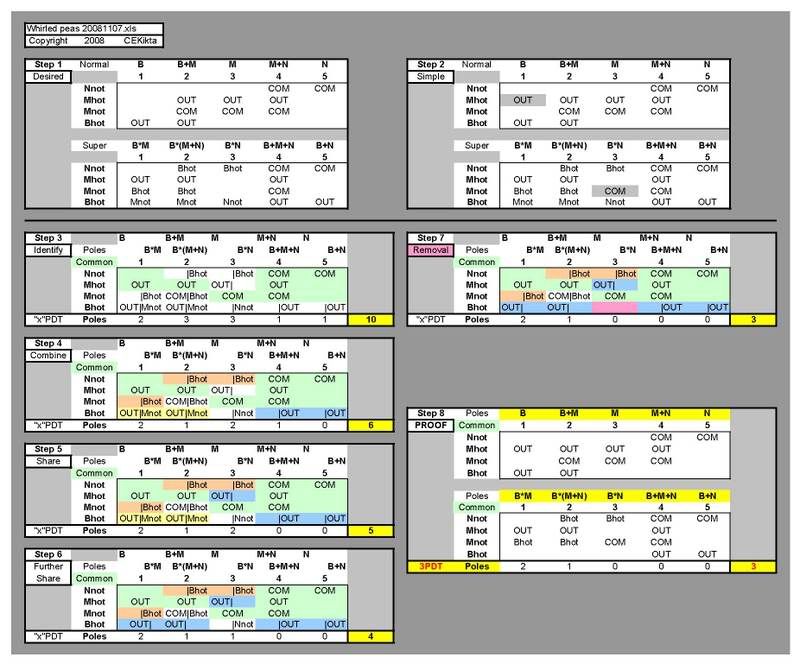 Oh woe and misery, I also can only find use for a 3PDT switch, but I believe that I realize your desired combinations in the desired order. Now, it's late and I've had a full day so I may still be lost in musing on interbrane quantum phasing, but I'll revisit this on the morrow since it makes way too much sense now. This is the path I would (and do) follow for most all designs. /pathNow, you may have done exactly this, but I don't "see" it. Done is.  No. The original Mike Richardson design is the second one of his that I posted. It did B+N and B*N in the middle position. This is the one that I drew for my design. The first Mike Richardson design that I posted (the modded mod) is the second one that he did adding M and B*(N+M) in place of B+N and B*N. |
|
|
|
Post by JohnH on Nov 8, 2008 18:12:21 GMT -5
Chris I found it most interesting to see how you logically analyze such a circuit to deduce an optimum design, thouigh I confess it took me a few goes to see what was happening. So on the principle that it is more effective to seek forgiveness than permission, I had a go at sketching out what an actual schematic would be based on your analysis:  And it looks like it would work like it says on the packet!. There's a few more 'hanging hots' implied than mine, so screening needed as usual. But that was a good learning experience so thanks and +1. cheers John |
|
|
|
Post by ChrisK on Nov 8, 2008 21:36:23 GMT -5
I've taken the path of proving the possibility of a complex design before I draw a trace. By knowing the possibility of success (or at least the minimum number of poles and positions), I can at least get into the right ballpark first.  My focus was on the minimum number of poles on the secondary switch (it was a challange to beat 8 poles after all). One could revisit the analysis to see how a 4PDT decreased those hanging about. Also, one could revisit for shorting any hanging coils when not selected. I drew up my design in AutoCAD. It works as the analysis indicated. 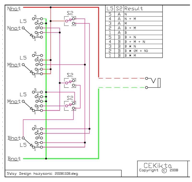 Proof is. |
|
hazysonic
Rookie Solder Flinger

Posts: 13
Likes: 0
|
Post by hazysonic on Nov 9, 2008 23:44:43 GMT -5
No you're right, I was using a shotgun approach  , but I'll be doing it this way from now on. Thanks for the solid explanation---that will be helpful over and over again in the future. The circuit looks great too... I had no burning desire to use an 8PDT switch so I'm happy to find a better way and learn something along the way. I plan to use a toggle switch to change modes, and maybe a push-pull pot to flip the neck phase. I have a humbucker in the bridge which already has a switch for humbucking/single, which I plan to change to humbucking/parallel/single. |
|
hazysonic
Rookie Solder Flinger

Posts: 13
Likes: 0
|
Post by hazysonic on Nov 21, 2008 11:41:16 GMT -5
So I've been working on this more and decided I better audition the sounds before wiring it up. Some of the sounds that I thought would be great were lame and vice versa. I also had a friend give me a 4P3T switch, which got me thinking about trying to eliminate the need for a phase switch altogether. I would rather think in terms of sounds that I can quickly access instead of thinking about what combination of 3 switches (5 pos, toggle, phase) I need to get the sound I want--two switches is better than 3. So here is my attempt at using ChrisK's method, but I'm not totally sure how to reduce the poles when they are 3T:  On the switches, I'm permanently using one pole to allow b- to be used OOP and in serial in certain combinations. Also, I thought I may need to use both the terminal side and the individual poles, so I've designated these by the switch name (s1, s2, s3, s4), and the individual poles of each (s1a, s1b, s1c, ....) I don't mind changing the order somewhat to accommodate simpler wiring, although I did like having stock sounds on the first position and the more obscure ones ( m*(b+N), b*M) on the 3rd position. And for what it's worth, here are my descriptions of the sounds and what I would use them for. I'm using all dimarzio in my HSS: PAF36 anniversary, virtual vintage area 58, virtual vintage area 61. + for parallel, * for series, lower case for OOP N*(B+m) - thick and complex tone B+M+N - different flavor of strat tone, i liked better than B+N M*N - for chime-y hot lead tones N*(B+M) - a very thick tone B*N - for thick leads m*(b+N) - AM radio sound b+M+N - sparkly m+N - a quacky sound b*M - sound for breakdowns, funky m*N - for layering guitars in the studio |
|
|
|
Post by ChrisK on Nov 21, 2008 22:21:46 GMT -5
What exact type of 4P3T switch (rotary, ON-ON-ON, etc.)? BTW, a 5P5T switch only exists in lever form Europe (Schaller MegaSwitch "M")? This data refers to the stacked 8 pole version. www.eyb-guitars.de/Eyb-English/Megaswitch_files/English%20Megaswitch%20M.pdfI have queried them thereon. You refer to 10 combinations here, but show 15 in the worksheet. I don't see the correlation to the sheet of 15, the switches 1 thru 4, and the 10 combinations. So I don't quite "see" the attempt at using my method, which it to enumerate the combinations per bank of 5-way switch positions. I then position each bank above the others and look for similar structures with minor changes. In step 1 to step 2 in my post, I added some harmless connections for the middle pickup in anticipation of simplification for step 3, which shows the "left-normal" and "right-super" positional changes needed. Between these two choices for a particular terminal (initially only 10 in number - NOT 20 which would be the case if all non-pole terminals had multiple selections needed), a unique pole was needed for each. A quick look infers the following; It appears that you have three banks/groups for the 15 combinations. Looking at b-, I can see that it indeed does not require a separate pole on the lever switch, but only the bank switch if the grouping of the 15 combinations remains as you have shown. That being said, the initial tally indicates the following number of poles on the bank switch; Neck -, 5, easily reduced to 4 Middle +, 2 Middle -, 2 Bridge +, 3, combined with 1 from Mid -, 2 Bridge - ,1 TOTAL = 11 = 10P3T on bank switch, 4P5T on lever I will not look to further reduce this until you confirm the combinations and positions. BTW, I am building a guitar with DiMarzio's; a FRED in the bridge, an Area 61 in the middle, and an Area 58 in the neck. The wiring in this is the The HSS All Mode 'Caster. |
|
hazysonic
Rookie Solder Flinger

Posts: 13
Likes: 0
|
Post by hazysonic on Nov 22, 2008 0:02:24 GMT -5
The table is layed out like your examples of steps 3-7 above, where you have 5 columns to show the 5-position switch, and further divided into columns to show the connections made in each of the three positions of the 2ndary switch (rather than putting them into the one column and using a vertical divider like you showed).
I followed your explanation for the earlier example but was having a hard time being so systematic about it with the 3rd position thrown in on the 2nd (it's a rotary) switch. I got as far as identifying poles required (thus the color codes). I also did attempt to identify similar structures, and positions that used the same connections.
also, the only reason i didn't mention the stock sounds was because I already know I want them and since everyone is already familiar with them. As it is I put all the stock positions on the 5-way when the 2ndary switch is in the first position.
well I need to head off to bed, thanks for taking a look. I'll look at this closer tomorrow and try to make some headway...
|
|
hazysonic
Rookie Solder Flinger

Posts: 13
Likes: 0
|
Post by hazysonic on Nov 22, 2008 9:31:54 GMT -5
oh, just realized i should clarify that I am still using a 4P5T switch. I put a 5th row on my chart so that I could easily see where the b- terminal is going, but it is using one of the poles of the 3-position switch...
|
|
hazysonic
Rookie Solder Flinger

Posts: 13
Likes: 0
|
Post by hazysonic on Nov 24, 2008 18:53:46 GMT -5
This has turned out to be quite the time consuming project... Here is my latest iteration which I believe should work. I sacrificed m*N, m+N, and b*M and added b+m+N, (M*b)+N, and b+N in order to make it work. I like b+N, but I do wish I could get m+N on there somehow in exchange for one of the other two I added.  Note that b- is on the 4P3T rotary switch, not the 4P5T switch, but is shown on the chart for convenience. All in all, I like all these sounds and the way they're grouped. I'll give it a day in case anyone has any suggestions or I find any errors, and then try wiring it up. One question this process has brought up regarding Chris's method (maybe I should post into a new thread)... I see how Chris is able to determine how many poles are needed for a particular arrangement using 4PDT and reduce them down, but I kept ending up with way to many poles (I think because I was trying to get specific combinations using the 3rd throw of the 2nd switch). Is there a good way to choose the best groupings (which must be done before systematically reducing and determining if it is possible to build). Or maybe my more general question should be: Is there a systematic approach to designing these schemes from start to finish, or only once the final desired order of combinations is established? |
|
|
|
Post by ChrisK on Nov 24, 2008 22:21:19 GMT -5
Only trial and error, or, as you go, you begin to "see" things.
I think that you should add another table for the xP3T rotary switch. It would label each pole and the three positions.
Otherwise, there is some guessing as to what things really mean.
|
|
hazysonic
Rookie Solder Flinger

Posts: 13
Likes: 0
|
Post by hazysonic on Nov 25, 2008 0:45:17 GMT -5
 note that although positions b and c are unassigned, I do use them to create connections. |
|
hazysonic
Rookie Solder Flinger

Posts: 13
Likes: 0
|
Post by hazysonic on Jan 2, 2009 3:50:48 GMT -5
thought I would update...
This project has been on the backburner (keys are my main thing), but I finally got it done enough to test, but the middle PU has low output for some reason, so I need to troubleshoot. Otherwise things seem to be in working order. In addition to the 15 sounds listed, I also added a kill switch and an on/on/on dpdt for the bridge PU. Soon as I can iron out the middle PU I'll post results and sound clips...
|
|