toddmaxx
Rookie Solder Flinger

Posts: 3
Likes: 0
|
Post by toddmaxx on Apr 1, 2020 11:03:17 GMT -5
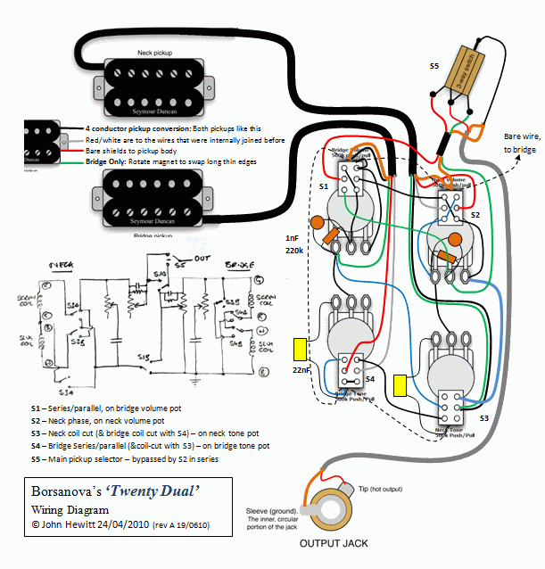
Hi OK thanks for your help. I would like to try the twenty dual project and also the lp-16 project on an epiphone. Since I would more than struggle with the electrical schematics, I will be relying on Johnh s wiring diagrams for both. I found one usable version of the twenty dual {dated 24/04/10} and wanted to confirm that this was the most up to date version. I also had a couple of questions regarding a couple of specifics. First, I notice that the orange/ black pup, and orange/orange pup/ switch seemingly attach to the "top" of the pots. My pots have a terminal in this location and I am unclear if these wires are connected to this terminal or soldered to the pot body. Also a similar question on the pot grounds, are they connected to the "top" terminal or the pot itself? The next question is regarding the pup notes. Im not sure what "bridge only: rotate magnet to swap long thin edges"means. Not sure what to do there. The last question is regarding the capacitors/ resistor. I purchased 2 @ 22nF capacitors, 2@ 1nF Capacitors and 2@ 220k =/- 1% resistors. Im not sure if I need something more specific. Additionally, I would also like to build the LP-16 set up for my Epiphone ,eventually, and would like to see the latest diagram in the Johnh format.. Im very excited and good at following instructions. But these will be my first guitar wiring projects, so any help and guidance are greatly appreciated. Thank you , Todd
|
|
|
|
Post by JohnH on Apr 3, 2020 18:05:52 GMT -5
Hi Todd Thanks for your posts. First, you may have noticed that all my GN2 images are currently 'between hosting solutions' and are therefore not appearing. I still have them all and the work-around I my sig below opens them. But fixing them properly (again) is getting nearer to the top of my to-do list. But lets post the one from this thread again:  This was 10 years ago, where I added a layer of extra thinking over Borsanovas design. Since then, Ive learnt a few things and forgotten more than a few. Lugs on back of pots = top of push-pull switches. Yes solder to those, they are part of the case of the pot and give ground connections. The parts you have are all fine, except a year or two later, I came to the conclusion that for the treble bleed circuits, a 150k is a bit more consistent than 220k. The magnet flipping is about taking out the magnet from one pickup and reversing it so that the two screw coils have opposite polarity. Maybe you don't want to do that, its not essential and the design could be amended to avoid it. Also, Im seeing a couple of issues on the diagram that may need fixing. Ill look at it some more.... The other design, this one (there are other diagrams too)…..: www.jocidapark.com.au/circuits/GN2/Lpx1-071109.png….is far simpler and is the one I have myself, and haven't wanted to change it in over 10 years. |
|
toddmaxx
Rookie Solder Flinger

Posts: 3
Likes: 0
|
Post by toddmaxx on Apr 4, 2020 13:25:57 GMT -5
Thank you so much for your attention. I know this is old news for you. It was very intimidating to feel that I could only access some of your diagrams, thus my measure 6x, cut once post. I will order the 150k s today and will await any other adjustments that you recommend. In addition to this wiring project, I will be winding and wiring my humbucker bobbins as well. Any suggestions on an ideal wind for the wiring will also be appreciated. I will keep the projects separate until Im sure each part works independently to avoid total chaos. I guess it would be most helpful not to assume that I know anything. So the more obvious and clear, the better. Ive done a few other soldering projects, but no guitar projects. Im incredibly excited to take on this whole project and very thankful that there are others who are willing to help.
|
|
|
|
Post by armandhammer on May 20, 2020 23:11:31 GMT -5
Newbie alert. I just did Borsanova's original Twenty-Dual Master (not mix) mod on my Epiphone SG Pro. I'm encountering one small issue: the tone knobs on both pickups seem to only really have an effect at the 9.5 to 10 range. So moving from 1 to 9.5 all sounds the same, then when I turn past 9.5 it radically alters the tone (almost like flipping a switch). All the pots are CTS P/P A500K. I have a 22n cap and 33n cap on the pots (can't remember which is on Neck and which is on Bridge).
Why would the Tone pots have such limited range? Is it because the stock Tone knobs are B500K and this is just what happens when you swap them for A500K? Everything else on the mod seems to work, the overall sound is fantastic, and honestly the Tone limitations don't bother me too much, but it would be nice to get some more range so it feels like I'm adjusting something instead of basically having just 2 actual tone settings on each pot. I tried to get B500K P/P but they are really hard to find and it seems CTS doesn't even make any with that taper.
Is there some hack that I can do to make the A500K behave more like a B500K, if indeed that is the problem?
|
|
|
|
Post by reTrEaD on May 22, 2020 10:19:46 GMT -5
Is there some hack that I can do to make the A500K behave more like a B500K, if indeed that is the problem? Not really. In voltage divider configuration like a volume control, you can change the law of a pot. But in this application, that won't work. I'm rather surprised to hear the symptoms you're describing. Yes, an audio taper pot will have less fine control at the clockwise end of the rotation than a linear will. But for it to be switch-like is very much unexpected. Are you using the correct lugs for the pots of pots the tone controls? (the wiper and counter-clockwise lug) if you use the wiper and clockwise lug, I would expect that to result in somewhat of a switch-like action. But in that case, fully clockwise would be full treble-cut. |
|
hipher
Rookie Solder Flinger

Posts: 4
Likes: 0
|
Post by hipher on Sept 16, 2020 2:46:00 GMT -5
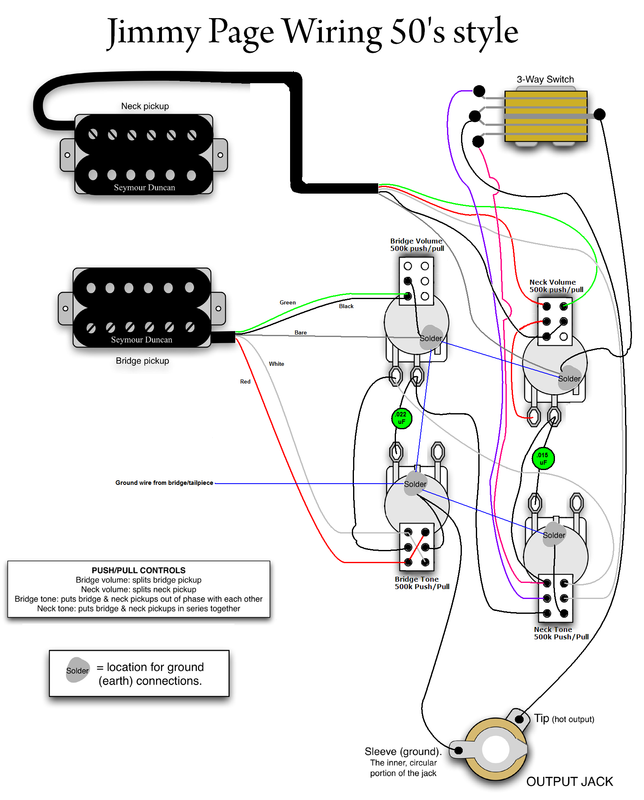
Hello everyone. New to the forum, I found it while trying to find a JP wiring, as there are so many of them, often without proper explanations on what does what. It seems not to be the case in this thread, a lot of electrical engineering wisdom condensed in a few pages  Nevertheless, I was looking for a wiring shceme with 50's style wiring, the tone capacitor at the output of the volume pot, and not at the input. Can I just follow the wiring shared here but change the wiring of the tone capacitor/pot, leaving everyting else the same? Or will I mess something? I can follow the wiring logic for the different switch combinations, but don't know what effect on tone, impedance, etc, my proposed modifications would have... Thanks a lot. |
|
|
|
Post by frets on Sept 16, 2020 8:13:01 GMT -5
Hi Hipher, I have this ‘50’s style Jimmy Page. Please know it’s not an easy build. I think it is difficult. Welcome.  |
|
hipher
Rookie Solder Flinger

Posts: 4
Likes: 0
|
Post by hipher on Sept 16, 2020 14:26:55 GMT -5
Hi Hipher, I have this ‘50’s style Jimmy Page. Please know it’s not an easy build. I think it is difficult. Welcome.  Thanks! I will take a look in detail, I like to know what's going on for each switch combination. I'm pretty sure I will end up using only a few combinations, but since I'm replacing the pickups by ones with 4 wires, I thought it does not harm to have more possibilities to choose from. |
|
|
|
Post by frets on Sept 16, 2020 15:13:50 GMT -5
Hipher,
I have a better diagram, I just need to find it.🙃. Just hang on because I’ll eventually find it.
|
|
|
|
Post by frets on Sept 16, 2020 16:16:25 GMT -5
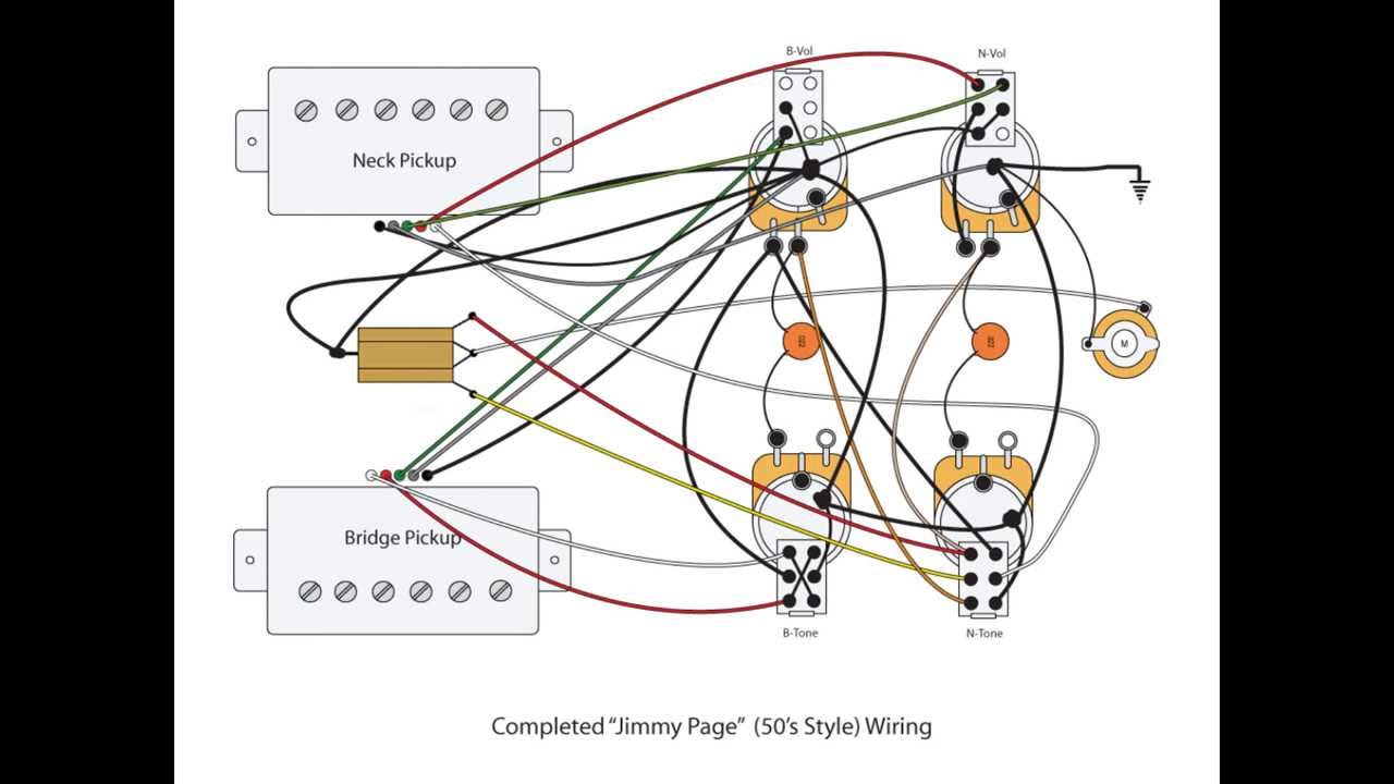
Hipher, Here is the best ‘50’s Jimmy Page I have. Be aware that it can only do Series and Phase when the pickup switch is in the middle; I.e. both pickups “on”. -The Bridge Volume in the Up position places the Bridge Pickup into Coil Split; -The Bridge Tone in the Up position results in Phase to the Bridge; -The Neck Volume in the Up position places the Neck Pickup into Coil Split; -The Neck Tone in the Up position results in Series. When I am asked to wire this, I always use Paper-In-Oil Caps and I use 22nF on the Bridge and .015nF on the Neck Tone. But you can use Orange Drops or “Greenies” or other capacitors. You can also wire it so both Tones are 22nF. Whatever value you like. NOTE: The wire colors are Seymour Duncan’s.  |
|
hipher
Rookie Solder Flinger

Posts: 4
Likes: 0
|
Post by hipher on Sept 17, 2020 0:32:16 GMT -5
Hipher, Here is the best ‘50’s Jimmy Page I have. Be aware that it can only do Series and Phase when the pickup switch is in the middle; I.e. both pickups “on”. -The Bridge Volume in the Up position places the Bridge Pickup into Coil Split; -The Bridge Tone in the Up position results in Phase to the Bridge; -The Neck Volume in the Up position places the Neck Pickup into Coil Split; -The Neck Tone in the Up position results in Series. When I am asked to wire this, I always use Paper-In-Oil Caps and I use 22nF on the Bridge and .015nF on the Neck Tone. But you can use Orange Drops or “Greenies” or other capacitors. You can also wire it so both Tones are 22nF. Whatever value you like. NOTE: The wire colors are Seymour Duncan’s.  Thanks! I will give it a try! |
|
hipher
Rookie Solder Flinger

Posts: 4
Likes: 0
|
Post by hipher on Oct 15, 2020 11:36:41 GMT -5
OK, finially managed to finish wiring my semihollow with the JP 50's style wiring. I went crazy slow double checking against the diagram at every step to make sure I did not mess it up. I think I have not   Anyway, I have been testing the setup before installing it trhough the f holes, which will a big pain, so I don't want to do it more than once. As I don't yet have even the bridge installed, I've tested only by tapping the pickups with a screwdriver. Everything seems as much in order as I can check like this, except that with the 3 way switch in the middle, if I roll down to 0 one of the volumes, I get no output at all, regardless of wich one. If I think of if electrically, I guess it makes sense, as I'm grounding the output of the corresponding pickup, and since both are connected though the 3 way, the other one is also going to ground...but I did not expect this behaviour. It's the first guitar I have with 2 volumes and 2 tones...and as soon as I got it I removed everything, so I don't even know if before that it worked the same. Is this behaviour normal? Or have I messed up the wering at some point? |
|
|
|
Post by JohnH on Oct 15, 2020 16:01:08 GMT -5
nice looking wiring!
The effect you describe happens on any normal wiring with two volumes and a toggle. With both pickups selected, and one volume at 0, that volumes centre lug is at ground and shunts the other pickup too. Its not a real problem, because if you want one pickup fully off, you can select just the other pickup using the switch. There are wirings that try to solve this but they cause more and worse problems instead.
I'm in awe of building this 'ship in a bottle' into a hollow-body! A full set of tests are a good idea.
Resistance tests can check a lot. Measure from ground to output, knobs at max. You should see close to 1x a full pickup resistance when one is selected x1/2 for both in parallel, x2 for both in series. All of those x1/2 with coil splits.
All of those values will be subject to your pickups , and about 1-3 % lower due to volume pots.
Then for any setting, sweep volume pots, which should give output resistance thats start as above at max showing the pickuo, rise to about 120-140 k at about 6 or 7, then fall to 0 at minimum.
Sweeping tone pots should never change output resistance.
On tap tests, a pickuo that is not involved in a setting should give no output at all. For an on pickup, if you split it, both coils of it may still give a thump since they are magnetically coupled, but one should be less.
Finally phase tests: Check out our reference section for the 'screwdriver pulloff test', and make sure every setting on all active coils are in the same phase , unless you pull the phase switch.
All those tests are actually very quick and together they give you a full diagnostic check ahead of installing.
|
|
|
|
Post by JohnH on Oct 15, 2020 16:14:49 GMT -5
The last few posts about 50's wiring schemes are a good discussion, but since tbis is currently in tbe schematic thread about Borsanovas designs, we may move them to their own thread. In the meantime, carry on...
|
|
willard
Rookie Solder Flinger

Posts: 2
Likes: 0
|
Post by willard on Feb 1, 2023 21:02:24 GMT -5
Hello.
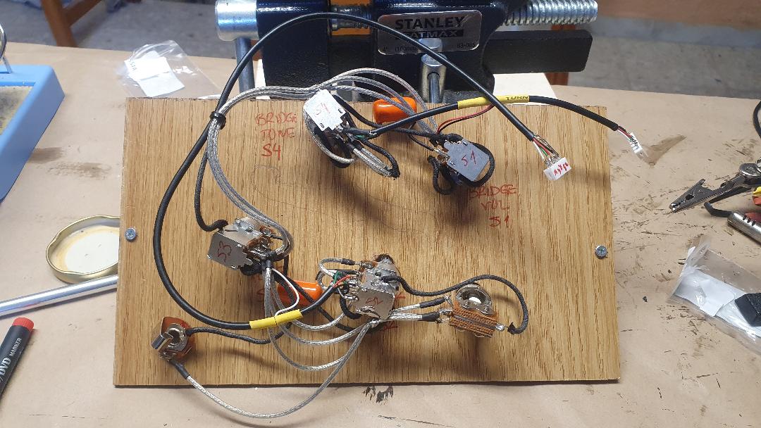
Just joined and dropped by to say that I have wired up the Twenty-Dual mix based on JohnH's version B diagram in post/reply #25.
I checked the results against Borsanova's specs given in post/reply #14. Everything works as designed. Just another data point for those considering it.
Thanks to Borsanov and JohnH for providing these to the public!
willard
|
|
|
|
Post by newey on Feb 1, 2023 22:50:41 GMT -5
willard- Hello and Welcome to G-Nutz2! Always good to get confirmation that something works "as built" and not just on paper. Thanks for sharing your experience with this design.
|
|
willard
Rookie Solder Flinger

Posts: 2
Likes: 0
|
Post by willard on Feb 4, 2023 18:52:18 GMT -5
willard- Hello and Welcome to G-Nutz2! Always good to get confirmation that something works "as built" and not just on paper. Thanks for sharing your experience with this design.
Nice to meet you.
It's the least I can do after reading and watching the big brains work through their process and give us the goods. I never could have designed it myself. My head just spins away from me ...  |
|
mrbauhaus
Rookie Solder Flinger

Posts: 1
Likes: 0
|
Post by mrbauhaus on May 6, 2024 8:36:47 GMT -5
Likewise, I have just build the same version (Twenty-Dual mix based on JohnH's version B diagram) and can confirm that it works correctly.
Many thanks for Bosanova and JohnH for their hard work and generosity of their contributions.
FYI, I put this is an F-hole Les Paul style guitar - it can be done! TBH, I broke the wires at least 10 times trying to get it in through the F-holes but got there eventually (I soldered a thicker copper wire around the pots to give it a bit more stability.
Love the variety of sounds - a bit disappointed that I built it for my son and have to give it away.
Maybe I'll build another (but no more f-holes)!
|
|
|
|
Post by newey on May 6, 2024 11:36:19 GMT -5
mrbauhaus- Hello and Welcome to G-Nutz2!Always happy to hear success stories. Please report back if you do build another for yourself!
|
|