|
|
Post by ChrisK on May 31, 2007 23:10:59 GMT -5
This is a wiring design that uses binary tree switching for coil selection. When both coils of a pickup (or both pickups at the higher level) are off, they are in series. When either or both are on, either or both (in parallel) are on. Examples are given for a single two-coil pickup (or two single coil pickups) as well as for two dual coil pickups with macro (next level) switching. Both SPDT (hanging coils) and DPDT (no such malady) schemes are shown. The model scales, but quickly gets out of hand (  for more than four coils. If one wishes out of phase combinations, one pickup should have a 4PDT fitted to effect this. 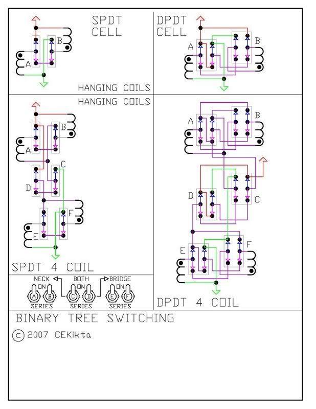 |
|
|
|
Post by michaelcbell on Jun 1, 2007 6:35:39 GMT -5
That's a really nice design - Flexible and intuitive, but not totally unmanageable. I hope it gets built by someone(derguy)
|
|
|
|
Post by JohnH on Jun 1, 2007 17:09:02 GMT -5
Thats a good piece of thinking. So from a pup, you can have series, one coil, other coil, or parallel. And the same pattern from the pup combos.
Thinking about programing it reminds me of a 'computer' we built at school in 1977.
To complicate its elegant simplicity:
Functionally, with the same number of switches, I'd like it so that when one of the coils is set in single coil mode, it always comes up in reverse phase. With this, you could arrange for the bridge pup always to produce single coil hum of the oppposite hand to that of the neck single coils, ie bridge would deliver, say, a North coil in normal phase of a south coil reverse phase, and neck would be vice-versa. This would give optimum hum cancelling and also humcancelling OoP combos. It would cut out non-humcancelling sc combos.
To do that, it would also be necessary to keep the in phase para combo on the pups. I could see it needing a 4PDT for each coil switch.
cheers
John (age 101111)
|
|
|
|
Post by michaelcbell on Jun 1, 2007 21:07:43 GMT -5
Well, from what I see, that's a big request, though if someone's up to it, ChrisK is  |
|
|
|
Post by ChrisK on Jun 3, 2007 14:51:29 GMT -5
:)NO.
|
|
onederboy
Rookie Solder Flinger

Posts: 19
Likes: 0
|
Post by onederboy on Jun 3, 2007 23:58:57 GMT -5
quick question, where do the tone & volume controls come in?
|
|
|
|
Post by wolf on Jun 4, 2007 1:55:25 GMT -5
This might be hard for you folks to believe but I have already built this - actually two of these- one about 6 months ago and the other a few months ago. Yes, I have my Gibson SG and Yamaha SBG 2000 wired in this way. So basically, I have already done it. I have always been reluctant to drill any holes in the SG but I figured this circuit would definitely be worth it. I forget how many extra holes I had to drill (probably 3) but if you remove most of those pots and that monster pickup switch, you don't have to chew up the guitar too much. I was preparing diagrams and trying to get a webpage going. I was also wondering about if it was patentable (probably not) so I was going to "publish" this on my website in probably a month. Anyway, so folks don't think I'm making this up, here are some diagrams I've already done: Here's an attempt (successful) of wiring a 2 humbucker guitar with 2 series parallel switches and 2 SPDT switches for the 4 pickup selections of neck/ bridge/ both parallel / and both series. I wired my OLP about a year ago like this:  Here's a neater diagram of that circuit:  The next 2 diagrams are the "ultimate" in this design. 6 SPDT switches are used in order to get one heck of a lot of switching selections: any 1 single coil can be chosen; neck- series or parallel; bridge- series or parallel etc. I find the most interesting choice is the inner coils in parallel or series. Hard to describe but nice sounding. The bottom diagram includes a phase switch which with individual selectable coils you have two choices of single coils with the same polarity and you can have each choice in series or parallel.  Do I have a picture of either guitar? No.  I don't have a digital camera and I haven't used my film camera in quite a while. Still, if you want to see I am not making this up, I could take a photo, get it developed in a few days, scan it and then post it. By the way, the Gibson SG looks really nice with 4 switches mounted on a brass plate and the 2 main switches on a silver plate. (Not really silver - I got a scrap of metal from an old electrical box and put it on the grinding wheel. Surprisingly it ended up rather nice). GEEZ it is late here. I just think it is incredible that someone else thought of this. (and gave it a name - Binary Tree Switching) I was going to call mine Super Seven Switching (if you use the phase switch) or Super Six Switching - (without) |
|
|
|
Post by wolf on Jun 4, 2007 2:15:43 GMT -5
|
|
|
|
Post by ChrisK on Jun 4, 2007 20:39:57 GMT -5
Nope, not at all hard to believe! They say that great minds think alike. I believe that great minds just think! Well, it's similar to binary tree logic and decoding. I called it Binary Tree Logic due to this. Its real value came from "since you (the switches in a binary tree scheme) aren't doing anything of value when off, when both of youse are off, do series. Then it extrapolated naturally/nicely. It's still too simple and expansive for my tastes (there be a lot of switches there mate). A natural place for this (aren't you sorry that you modified the SG) is on an "excessively knobular" guitar like an LP where you have a lot of push pull pots possible (P 4). This design (well, simplification of another design) was posted since I'd allowed (well, admitted) that I could do this as an alternative to the three-way switch for series/single/parallel here: guitarnuts2.proboards45.com/index.cgi?board=wiring&action=display&thread=1180267662It actually came about during my "slide switch" days in the past (man, are they cheap when you buy them NOT from guitar parts suppliers). I'd started with SPDT switches but quickly moved to the DP4T slides since they were simpler for me to operate. Slides were a great idea but I never could find any square drill bits for drilling the slots in the pick guards. A DP4T slide would handle all of these modes for two coils. Extrapolation is. Some past "efforts". A Strat with 3 DP4T slides; one for the bridge humbucker, one for the middle and neck single coil, and one fer betwixt. The last saved date on this file is 11Sep2002. (I actually do all of my guitar and wiring design/builds in AutoCAD with digitized body shapes for absolute fit and function. Then you just tape on the printed templates and drill away.) 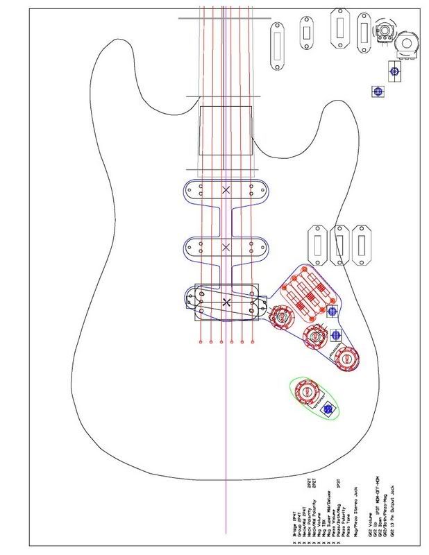 Some Tele stuff; With 4-way slides: 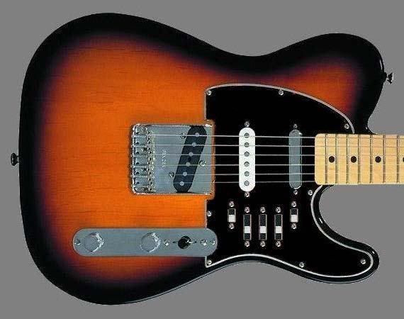 A slide switch version of the ToggleCaster (this pic has been "appropriated" by others in the past); 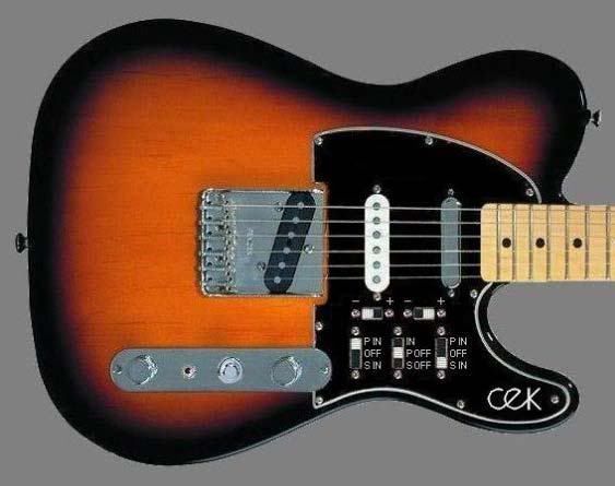 |
|
|
|
Post by ChrisK on Jun 4, 2007 21:27:52 GMT -5
That depends on how many there are and where you want them to be!
Modular is!
|
|
|
|
Post by UnklMickey on Jun 4, 2007 23:12:43 GMT -5
|
|
|
|
Post by wolf on Jun 5, 2007 0:27:23 GMT -5
If nothing else, I figured I'd scan the guitar.
It doesn't look great but here it is:

And here's a detail of the switches: I am not sorry I "modified" the SG (I've had it since 1980). The sounds you can get out of this (In My Humble Opinion) make it well worth it. ChrisK that's very nice work you did on those guitars. ChrisK and UnklMickey Thanks for the feedback. I trust we'll be talking about this again in about a day or so. UnklMickey - you changed your name didn't you?
|
|
|
|
Post by ChrisK on Jun 5, 2007 12:19:37 GMT -5
And since our perception of connected time began with the deployment of the internet, all that happened before "doesn't exist". It's hard to search for what isn't there (online). While we take great pride in our inventiveness, most likely we are just discovering stuff again for the first time (as we know it). I remember connecting pickups in all possible combinations in the 60's and trying to explain to others why this might be a good thing. Complex switching, heck, there were no multi-pole rotary switches smaller than a guitar back then. Most of the Alembic stuff from long ago featured "switch rashes". I'm sure that they didn't do anything remotely clever. It's hard to know and even harder to find documentation thereof, but most all things wiring HAVE been done before, and we unknowingly stand on the shoulders of giants as we practice "anew".  |
|
aquino
Rookie Solder Flinger
 dô-ôb
dô-ôb
Posts: 5
Likes: 5
|
Post by aquino on Sept 25, 2018 20:09:54 GMT -5
I realize this post is VERY old, but I think this idea is really interesting, and hope I can contribute a little to it.
I made a version of the SPDT circuit that does this. In order to implement that feature, each SPDT becomes a 3PDT. One pole wired like the original, the other two poles as a phase reverse switch. Both phase reverse sections are in series with each other. This way, when both switches are up or down, phase from one coil is reversed two times, and thus remains the same. When one switch is up and the other is down, the coil is out of phase - but, of course, this only has an effect if you flip up the switch that selects the phase reversing coil. Both pickups need to be wired differently: in one (say, neck), coil A goes through the phase sections; in the other (bridge), it's coil B.
I like this concept because unless you have a pickup with very different sounds from each coil (P-Rails comes to mind), turning just coil A or just coil B should make little audible difference (especially on the neck). I personally would probably prefer go a simpler route and get series / single / parallel options from just one on/on/on DPDT. But wiring this binary tree version should not only provide better hum cancelling but also enhance the instrument's tonal palette. I see nothing preventing this idea to be applied to the DPDT version – except the patience to solder four 4PDTs... Here's the wiring diagram (current status: untested. I double-checked it myself, but I may have missed something...):
Hope you find it useful!
|
|
|
|
Post by newey on Sept 25, 2018 21:15:06 GMT -5
aquino-
Hello and Welcome to G-Nutz2!
It is an old thread, but a popular idea, so thanks for your contribution. Looks like you have answered JohnH's prayer from so long ago!
I used a binary tree scheme on a 4- pickup Start build I did some years back. These schemes are a bit "switchy" in use, but I got used to it pretty quickly.
|
|
|
|
Post by pablogilberto on Dec 18, 2019 8:11:49 GMT -5
I'd like to develop a logical/mathematical strategy (using boolean logic maybe?) so I can do some wiring mods from scratch.
Can you share your thoughts on how to do this efficiently?
I'm checking the posts above but most photos are blurred?
Musical Instruments For Sale
Thank you!
|
|