lectrawood
Rookie Solder Flinger

Posts: 8
Likes: 0
|
Post by lectrawood on Jan 6, 2009 7:06:04 GMT -5
Hi, been lurking the forum for a long time and in awe at the technical knowledge presented here! I've learned a lot already and it's helped guide some of my projects to success. But, now I'm in over my head and need some pro advice.
Got a project instrument here with a pickup similar to a telecaster. I need to cut the bass frequencies with a hard wired cap/resistor combination, no potentiometer, to knock off everything below a cutoff frequency of 200hz. (It's actually a percussion instrument that has a pickup similar to a guitar and there is a thump issue, so no need for adjustable tone control, just want to permanently knock out the lows).
If I understand correctly, there should be a cap placed in series on the hot wire of the pickup and a resistor bridged to ground (is that right?). What will be the value and best type of cap to cut off below 200hz? And what type of resistor should be used?
I've read that a standard passive tone control will cut 6db per octave. If there are two in a row, will that cut 12db per octave and if so how will that affect the tone above 200hz and how would it be wired?
Very appreciative of any guidance you guys can provide!
|
|
|
|
Post by cynical1 on Jan 6, 2009 11:49:28 GMT -5
...It's actually a percussion instrument that has a pickup similar to a guitar and there is a thump issue... Not being as electronically savvy as some here I would address the "thump" issue empirically. How and what is this pickup mounted to? Is it possible to dampen or isolate it from the body of the instrument? Possibly a foam pad under the pickup, depending on mounting configuration, or tube spacers would eliminate the "thump". An example would be a similar thread Pickup springs rattling at resonant frequency?Someone else will be by on the electronics side to dazzle you with the high pass filter. Happy Trails Cynical One |
|
|
|
Post by ChrisK on Jan 6, 2009 12:09:56 GMT -5
Do you know the electrical specifications of this pickup (resistance, inductance, and inter-winding capacitance)? Do you have a manufacturer's specification sheet? "Everything" is a strong word. "Everything below a cutoff frequency of 200hz" indicates an absolute stop band, which is not really possible with passive components. Yes, and maybe. This one is easy; use a 1/4 w carbon or metal film resistor. No one can give you the absolute values without knowing the resistance, inductance, and inter-winding capacitance of the pickup, as well as all of the other elements in the passive signal chain including the instrument volume and tone controls (if applicable), the cable capacitance, and certainly the input characteristics of the amplifier (impedance, which needs to include the input resistance and capacitance). All of these components make up the passive circuit, in which all components affect each other toward the overall response. A standard single-pole RC filter will have a response curve of 6 dB per octave. Two in series will effect a 12 dB per octave response curve, except that, since these are interacting passive components, they really won't. Also, passive filters only reduce frequencies (we're not going to discuss the series LCR circuit here) so there is an insertion loss that will reduce the output signal. OK, here's the reality part; since ALL of the components in this passive circuit interact, stating any absolute values for you would be BS. If you can't post the specific component values for the pickup, amp, cable, and all other intertwined passive components in this passive circuit, I would suggest that you put together a test filter using a mix of capacitors and pots. This can reside between the output jack on the instrument and the input jack on the amp. Until I know some of the characteristics of the components, I can't give truly meaningful values to start with. I might start with 0.001 uF thru 0.01 uF and a 500K pot. Here is a guitar schematic that has both high-cut and low-cut tone controls. Now, knowing that this pickup is like a Telecaster pickup (which pickup, please), we could make some assumptions about your pickup. If we knew the amp model we could make some assumptions about this as well as the input cable (a 300 pF and up capacitor). Based on this, some pSpice (freeware versions available) models could be used to plot the probable frequency response curves for various configurations. This would give us some component values for testing. Guitar Electronics Modeling - pSpiceThis is not likely the simple answer that you hoped for. A simple fast way to reduce the low frequencies is to use a graphic equalizer pedal between the instrument and amp. These have both boost and cut functions in specific frequency bands, usually of +/-12 to +/- 15 dB. |
|
lectrawood
Rookie Solder Flinger

Posts: 8
Likes: 0
|
Post by lectrawood on Jan 6, 2009 17:01:21 GMT -5
Thanks very much, that lets me know there's a lot more to be figured out!
I've isolated as much body (actually frame) noise as possible.
The resistance is 5,400 ohms. I don't know how to find the inductance and inter-winding capacitance. I mentioned a telecaster pickup because the resistance is in that range and thought it might provide a reference point.
Here is the actual configuration - The instrument is a xylophone with 30 fender rhodes pickups wired in series, one for each key of the xylophone (humbucking, reverse wiring every other pickup to reduce noise). Each individual pickup is 180 ohms. They are spaced 1 3/4" apart from one pickup to the next. The entire pickup array is shielded with copper to ground. Each wooden key of the xylophone is fitted with a small magnet which interacts with the pickup when the key is struck. There is no volume or tone control in the circuit (haven't had a need for it but may add one at some point).
This is a one of a kind project I put together myself based on guitar electronics. I'm a guitarist and have limited knowledge of this stuff, but just enough to make it work. Overall, the instrument sounds great. But, it would sound better without the thump produced by the mallet hitting the key and residual frame noise. I can just turn down the bass on the amplifier, but would like to reduce those frequencies before it gets to the preamp. Looking for a roll off filter, not a hard cutoff, starting at 200hz. The lowest key is middle C and I want to reduce the frequencies below that point as much as possible.
I'm sending the signal into a Roland GT3, which outputs to a PA or keyboard amplifier, using various modeling and effects within the GT3. Not the greatest, but so far it works for what I'm trying to do.
Hopefully this will provide a little more info and lead to a good solution!
|
|
|
|
Post by newey on Jan 6, 2009 19:31:27 GMT -5
I think ChrisK's suggestion of an EQ pedal merits consideration. You could probably snag one on Ebay for $25. This would save you a lot of grief test-wiring RC filters, and would potentially allow you to "dial out" exactly the frequencies you (don't) want. Of course, caps and resistors are a whole lot cheaper than an EQ pedal. But you also have to consider your investment in time, If it costs $25, that's 2½ hours of your time at $10/hr. Can you do this- testing various RC combos, wiring it up- in that time? Do you value your time at ›$10/hr.? And, if the pedal doesn't do the trick, you can always stick it right back on Ebay. Who knows, you might even turn a profit . . .  |
|
|
|
Post by ashcatlt on Jan 6, 2009 23:53:33 GMT -5
Well, then again, what's the value of being able to say "I made that?"
An active filter would be relatively easy to build, and not much more expensive than the passive version. By going active you can find ways to make it independent of the rest of the circuit. Makes the calculations much easier. You'd also be able to achieve 2 (or more) pole response if necessary.
|
|
|
|
Post by JohnH on Jan 7, 2009 1:19:54 GMT -5
If you want to try a simple passive RC filter, I think you have enough info there to make a guess at suitable values. All things considered, my calculated guess at R and C values, (bearing in mind that the pup is somewhat like a single coil Tele pickup and the input is similar to a guitar amp input) would be about a 150k resistor and either a 10nF cap (to get negligible (-1db) roll off at the lowest note of Middle C = 256hz and about -9db fall at 50hz), or 4.7nF (for about 3db roll off at 256 hz and -15db at 50 hz).
Calculated guesses of what sounds good can be 100% off. So to experiment, those two caps, plus a pot of either 250k or 500k, and have a fiddle. That’s within the range of Chris’ suggestions too. With one of those pots and those two caps, I think you will find an optimum setting for a simple RC filter. I would not go with two stages in this case, due to extra losses, unless there's some active buffering.
John
|
|
lectrawood
Rookie Solder Flinger

Posts: 8
Likes: 0
|
Post by lectrawood on Jan 7, 2009 2:40:20 GMT -5
Excellent info and ideas. Thank you all.
I'll get the suggested caps/resistors and give it a try. At least now I have a starting point and that's great!
An EQ pedal is certainly a possibility. Been using EQ within the GT3, but that's very noisy and the reason I'm looking for other solutions. But, there must be quieter pedals out there, so I'll dig into that. Also trying to keep things simple, so I can plug and play anywhere without necessarily having to include extra gear.
|
|
|
|
Post by ChrisK on Jan 7, 2009 20:36:09 GMT -5
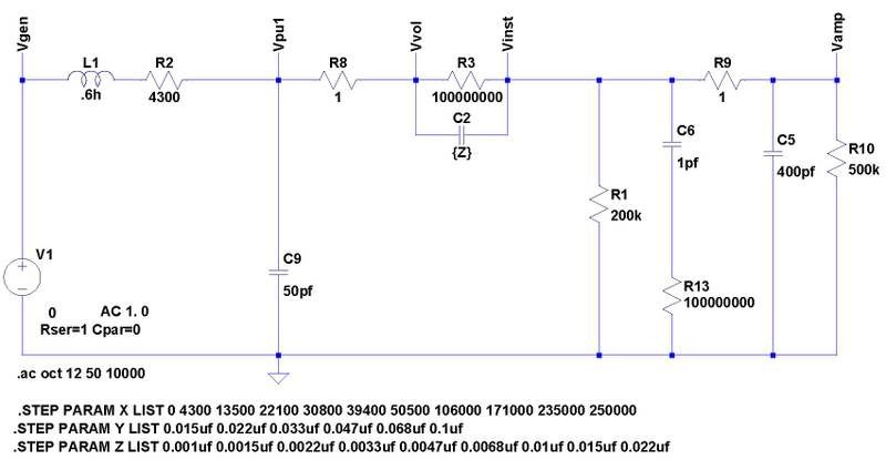
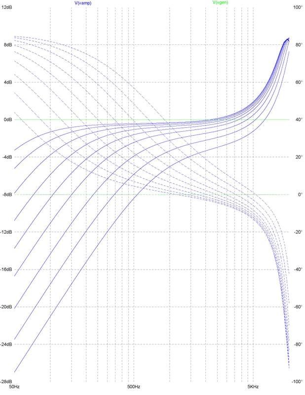
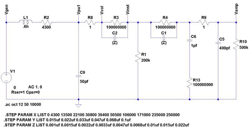
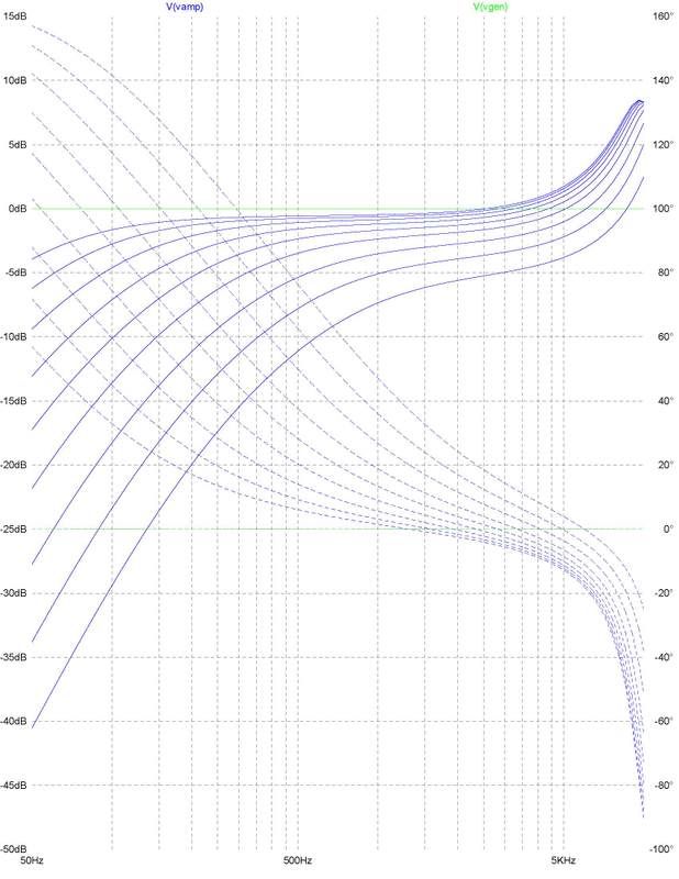
Regarding it as reference point, yes, but really, no. "The DC resistance of a pickup tells you as much about a pickup's tone and output as the shoe size tells you about a person's intelligence!" Bill Lawrence  The inductance of the pickup structure (all of them in series) will likely be much less than a guitar pickup since all of the coil(s) turns are not on the same coil and hence, are not part of the same integral inductor (inductance is related to the number of turns ^2). Conversely, the inter-winding capacitance may be quite different as well. Does each coil have a ferrous core? Maybe a delay-on gate circuit might help since this may be attack-related. Is there an issue with the far end (or struck end) of the tone bars/keys having too much (or not enough) travel when being struck? Is it an issue of the felt/foam padding under each tone bar/key? Also, of the padding on top of each tone bar/key (under the fastening screw head)? The "resistor" is in effect in parallel with the amp input. You may or may not need this. Adding the resistor will limit the harmonics produced, but this type of instrument may be more fundamental in nature that a guitar ("fundamentally", most instruments sound like a flute except for the envelope). The pickup is an AC generator in series with its inductive reactance, its resistance and this structure is driving its inter-winding capacitance to signal ground. It's a series LCR circuit. The low-cut cap is in series with the signal from the pickup going to the resistor going to signal ground, and the output jack tip terminal. In essence, the cap is a frequency dependent capacitive reactance that forms a complex (plane) voltage divider with the generator and its series inductive reactance and resistance, driving the amp and resistor as a load to signal ground. Since the pickup is really 30 individual pickups with 1/30 the number of turns of a Tele pickup, we might assume that the inductance is much less. If the structure was identical (which it is not), it would 30^2 or 900 times less. As a WAG, let’s guess that if a typical Tele pickup was 4 henries (it’s not, but it’s an average of many), we might surmise that it could (not would) be 5 to 20 mH. If we picked 20 mH, the series total would be 600 mH. This is the design model for a single series low-cut capacitor. The pickup inductance is set to 600 mH, its series resistance to 4300 Ohms, and the inter-winding capacitance to 50 pF. The cable capacitance is set to 400 pF and the amp input resistance to 500 K Ohms. The “resistor”, which in this model is in direct parallel with the amp input resistance, is set to 200 K Ohms.  For a series capacitor range of 0.001uf, 0.0015uf, 0.0022uf, 0.0033uf, 0.0047uf, 0.0068uf, 0.01uf, 0.015uf, and 0.022uf, the following curves result. Ignore the dashed curves, as these are phase information which will just confuse me. The larger the capacitance, the less the attenuation. The vertical dashed grid lines from 50 Hz to 500 Hz are 50 Hz each. The peaking beyond 5 Khz is related to the series LCR circuit formed by the cable capacitance and my bad guesses as to component values, and therefore out of scope for this discussion.  Note that the response results in less attenuation than JohnH indicated, again from the component interaction in a passive (lossy) circuit.  This is the design model for a dual series low-cut capacitor. The pickup inductance is set to 600 mH, its series resistance to 4300 Ohms, and the inter-winding capacitance to 50 pF. The cable capacitance is set to 400 pF and the amp input resistance to 500 K Ohms. The “resistor”, which in this model is NOT in direct parallel with the amp input resistance, is set to 200 K Ohms. The amp input resistance forms the second pole’s “resistor”.  For a series capacitor range of 0.001uf, 0.0015uf, 0.0022uf, 0.0033uf, 0.0047uf, 0.0068uf, 0.01uf, 0.015uf, and 0.022uf, the following curves result. Note that the response does improve somewhat with a two-pole filter.  Anyway, this exercise will show the general response effect of various series caps in a SWAG circuit estimate. |
|
|
|
Post by JohnH on Jan 8, 2009 3:40:28 GMT -5
From Chris' graphs, you can see it all.
For the values I used, there seems to be about 1 db of differnce at 50hz, but I did my numbers with a total load of 130k (150k resistor in parallel with a 1M input impedance), which is a bit more than Chris' 200k and 500k (143k combined).
So its all true
John
|
|
lectrawood
Rookie Solder Flinger

Posts: 8
Likes: 0
|
Post by lectrawood on Jan 8, 2009 7:39:21 GMT -5
Excellent, Chris, can't thank you enough! It's a lot to wrap my electronically challenged brain around, but I understand the data and schematics and will work with it over the next week.
Yes, each pickup has a single ferrous slug in addition to the core magnet.
There are definitely physical design issues. The keys are suspended on cord, and wooden slats which run the length of the instrument holding the supports for the cords resonate somewhat, even with efforts to mute them. Some of that vibration makes it's way to the keys and also to the mounts which support the pickups. Multiply that resonance through 30 pickups and it becomes substantial. The pickups are rubber mounted and the cotton cords which support the bars absorb some of the impact.
Alternate reverse wiring of the pickups, while keeping the magnets all in the same alignment, cancels out frequencies common to each pickup and has reduced frame noise by about 15db over a non-alternating design. But, there is still room for improvement and filtering of one kind or another will help.
Yes, excessive downward key travel is also a contributor. That vibration is below hearing range, but it affects speaker cone travel and clarity. Looking into other ways to support the keys which would be more electro friendly than a traditonal xylophone frame, but that's a major re-design that will take a while.
Hopefully, whittling away at these issues from a few different angles will make some improvements. I'll keep you posted on the progress.
|
|
lectrawood
Rookie Solder Flinger

Posts: 8
Likes: 0
|
Post by lectrawood on Jan 9, 2009 4:33:17 GMT -5
Wow! Amazing what a 99 cent cap can do. The .0047uf cap with a 1/4w 150k resistor works best so far. There is a little signal reduction, but barely noticeable and it's definitely a worthwhile trade off. Still experimenting and trying different combinations, but it's really doing the trick. The difference is impressive. You guys are AWESOME!
|
|
lectrawood
Rookie Solder Flinger

Posts: 8
Likes: 0
|
Post by lectrawood on Jan 11, 2009 7:27:44 GMT -5
Another question which may be a loaded one...
Ceramic or Mylar for this application?
Tried both and maybe I'm psyching out on it but seem to hear a slight difference, the mylar being more "neutral" and the ceramic creating a slightly thinner color, both good, just a little different. Curious to hear opinions.
Also noticing that the 150k resistor seems to sound a little beefier than 200k, or am I imagining? Curious as to theory suggesting which is better suited.
|
|
|
|
Post by JohnH on Jan 11, 2009 15:34:38 GMT -5
lectrawood - on the cap types, Chris has a more informed view but you may be hearing the difference between caps at different ends of the tolerance range even if they are nominally the same value. The tolerance can be quite wide. They also have various other slight characteristics and imperfections, such as resistance and inductance that may affect the sound very very slightly between types. I wouldn't have guessed that you would notice this however. The best way to judge is to have them both wired so you can change very quickly between them in an A/B test.
For a given cap, changing the resistance from 150k to 200k should give you a bit less attenuation at middle C, and a bit less reduction of the thumps. In a guitar, it would also give a very small increase in high treble. Id expect this to be much less evident in your case however, due to your probable lower inductance of the pickup and likely less zingy sound.
Congrats BTW, I'm glad its basically working!
John
|
|
|
|
Post by ChrisK on Jan 11, 2009 22:24:53 GMT -5
Well, Chris certainly thinks that he has a more informed view.....
I'm of the opinion that both of these are in appropriate for quality audio circuitry. But then, I'm a snob because I know why these are inferior.
Ceramic is similar in dielectric material to piezo pickups. There have been studies (by real engineers, not audio flufferpuckey merchants) that indicate that the size of a ceramic substrate changes physically when an electrical charge is placed across it. This changes back while the charge dissipates. This is the piezo part. (Remember discussions a'board about a piezo crystal being predominantly capacitive in characteristic?)
In other words, there is a memory effect that affects the sound quality thru a delayed (and hence non-linear) action.
Ceramic bypass capacitors such as a Z5U type can have significant leakage (which manifests itself as a parallel resistance effect) as well as a -20/+80% tolerance.
Mylar capacitors are also not high quality. They have what's known as dielectric absorption. The complete charge is delayed in its ability to be discharged into a load once the applied charge is removed. Again, a non-linear memory effect. This is most evident in high voltage capacitors (such as 10 KVDC) which come shipped with a shorting wire wound across both terminals. After Hi-Pot testing, the cap is shorted. Even if the voltage is zero, if left unshorted, the charge can eventually climb to hundreds of volts.
Since these effects are time-based, the effect varies with frequency.
It's similar to a motor is a generator, a generator is a motor (DC et al).
Now, there are some excellent mylar and ceramic capacitors. I know where to get them and how to read their spec sheets.
However, most folk are not electrical engineers and most guitar parts vendors are not going to sell the best parts, but the cheapest parts. Most of the generic mylar or ceramic 0.022 caps used in the industry cost less than $0.05 in thousands. They're sold for $0.25 to $1.00.
I tend to use OEM polycarbonate or polypropylene caps because I can, since I have access and knowledge regarding their electrical specifications.
Most capacitors used in vintage guitars were used not because they were excellent capacitors, but because they were cheap capacitors. The defects native to such are often the effects cherished for their vintage sound.
I can tell you if a cap is lousy or good; I can't tell you if it will definitively sound lousy or good in your application.
But, John is most correct; unless one can immediately A/B switch between components under test, during THE SAME AUDIO EVENT (such as one sustaining string pluck), any comparison is highly suspect and likely hydrogenated felderpucky.
(Never underestimate the ability of a human to rationalize, especially if they've spent coin serious on audio flufferpucky.)
|
|
lectrawood
Rookie Solder Flinger

Posts: 8
Likes: 0
|
Post by lectrawood on Jan 12, 2009 15:25:09 GMT -5
Great info.
Found a mail order source for polypropylene caps, but the shipping is an arm and a leg, so sluffing along with mylar til I can find better caps locally.
Thanks again!
|
|
|
|
Post by ChrisK on Jan 12, 2009 18:37:35 GMT -5
Don't forget www.digikey.comThey only list 3,712 different polypropylene caps. search.digikey.com/scripts/DkSearch/dksus.dll?Cat=131088&keywords=polypropyleneor www.mouser.comNeither of them rape and pillage on shipping charges. They are both OEM component suppliers so you'll have to get used to not paying exorbitant prices. ;D ;D They also have full data sheets on what they sell, but I must caution that having actual, real, and meaningful data causes most human brains to explode. Especially since words like "warm, deep, full, ethereal, middy, fuzzy, chimey, quacky, vintage, and oxygen-free" are not to be found. |
|
lectrawood
Rookie Solder Flinger

Posts: 8
Likes: 0
|
Post by lectrawood on Jan 13, 2009 3:22:53 GMT -5
Ah, that's much better than the $14.50 the other company wanted to ship a couple caps. Although they did offer to include a few adjectives with my order! ;D
|
|