|
|
Post by newey on Jan 24, 2009 21:14:45 GMT -5
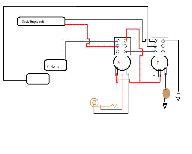
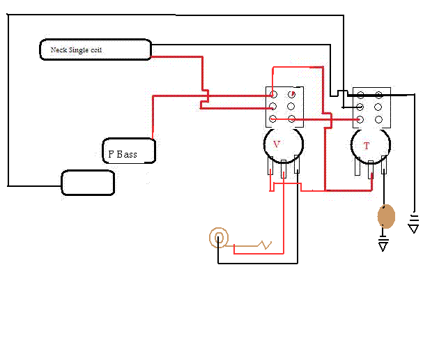
In the fairly early stages of my P Bass rebuild. I was convinced to use a Strat SC pup based on the discussion here. I came up with this for the wiring, using 2 push/pull pots for the switching so as to keep the stock P bass look. It uses the binary tree switching arrangement to give neck SC alone/P-Bass pup alone/ both series/both parallel.  Can someone vet this for me please? I tried to translate this from ChrisK's modular design for 2 SPDTs to the push/pulls, not quite sure I've got it right. |
|
|
|
Post by JohnH on Jan 24, 2009 21:37:06 GMT -5
Some more wires please!
When you pull on the volume pot switch, neither pup is connected. and how about the grounded lug on the tone pot switch? - which is not connecting to any other lugs
cheers!
John
|
|
|
|
Post by newey on Jan 24, 2009 22:27:03 GMT -5
Thanks! Back to the drawing board. EDIT: Better? |
|
|
|
Post by ashcatlt on Jan 24, 2009 23:06:09 GMT -5
Looks like it'll get you the options you've listed. It's not the most intuitive switching arrangement, though, is it? Also, it leaves the P-bass pickup hanging from hot when the SC is selected alone.
|
|
|
|
Post by newey on Jan 24, 2009 23:22:44 GMT -5
No, it's not. But it's essentially one module of the 2 on my (almost-done) 4caster, so I figure I'll get used to it. The pup hanging from hot ought to be solvable. The day when I can get these things right from the start is still a long way off. So, on to v3.0. Thanks for your help! You and I seem to have the "Battle of the Cheap Bass Rebuilds" going here.  |
|
|
|
Post by pete12345 on Jan 25, 2009 8:10:44 GMT -5
It's not the most intuitive switching arrangement, though, is it? I don't know about that- depending on which way up you wired the switches, you could have it so you pull up a pot to switch each pickup on, with both down being the series setting. Lay it out so that the pot controlling the neck is closest to the neck etc and its fairly intuitive  |
|
|
|
Post by wolf on Jan 25, 2009 15:01:09 GMT -5
Hi newey,
Not that I'm the Rembrandt of this message board but I'd like to redraw that diagram for you. If nothing else I'm a big fan of "binary tree" switching and I've wired seven double humbucker guitars with that circuit. (So basically, I've wired the binary tree circuit 14 times?)
For one thing, what is that rectangle to the bottom left of the P-Bass coil? Could it just be eliminated, along with its one wire?
|
|
|
|
Post by newey on Jan 25, 2009 15:27:33 GMT -5
Appreciate the help, Wolf! That's the other coil of the split-coil P bass pup. It could be eliminated, as it's just a graphic representation. But the signal return wire from the pup can't be eliminated! Or, 1110 times (binary is . . .)  |
|
|
|
Post by cynical1 on Jan 25, 2009 16:46:49 GMT -5
Or, 1110 times (binary is . . .)  01000011 01101100 01100101 01110110 01100101 01110010 01000010 01101111 01111001 Happy Trails Cynical 01001111 01101110 01100101 |
|
|
|
Post by wolf on Jan 25, 2009 19:05:19 GMT -5
Okay, here's the new diagram:  I think by adding a few more components, you can get free HBO. ;D |
|
|
|
Post by newey on Jan 25, 2009 19:28:05 GMT -5
Thanks for the redraw, Wolf. But this goes back to my first iteration, which JohnH found wanting. I originally was going to use both halves of the switch, but forgot to jumper the 2 poles together. In the second version, I just ran it all off one pole. I still have the hanging hot problem that Ash pointed out. More like a Chagall, I would say.  |
|
|
|
Post by ChrisK on Jan 25, 2009 23:41:12 GMT -5
Sigh.  You buy them books, you send them to school, and they eat the teacher.... Fun With Toggles & Push-Pull Switches take 2 sections "B" or "D". "B" shorts the coil hanging from hot when not selected. "D" shorts both when not selected. This takes a SPDT for each coil. If one doesn't want to short a coil when deselected, use Binary Tree Switching with the DPDT switches (upper right corner). |
|
|
|
Post by wolf on Jan 26, 2009 0:06:35 GMT -5
Okay, here's the revised drawing (before Chris K's posting was reviewed)  |
|
|
|
Post by cynical1 on Jan 26, 2009 1:55:43 GMT -5
If one doesn't want to short a coil when deselected, use Binary Tree Switching with the DPDT switches (upper right corner). Okay, just for academic purposes...and not that I'm qualified in any way to chime in here...but we're talking about this diagram below, correct?  If so, then is this the correct iteration for plan?  Again, not trying to sound competent, just trying to understand... Happy Trails Cynical One |
|
|
|
Post by newey on Jan 26, 2009 6:38:11 GMT -5
You guys move fast- I hadn't even had the chance to redraw mine and now I've got 2 versions! Thanks wolf, that's got it. And, Cynical!- your drawing is, I believe, correct so as to eliminate the hanging hots. And Chris- I knew you had a DPDT version to eliminate the hanging coils. Since push/pulls only come as DPDTs, I figured I might as well use the other pole to eliminate the potential problem. I just hadn't had the chance to go back and redraw it. Thanks to all who helped, I think this design is "in the bag", so to speak. And ChrisK said: I, for one, am no Alfred Packer. |
|
|
|
Post by newey on Jul 5, 2009 19:42:40 GMT -5
Okay, back on this project so I bumped this thread . . .
I'm ready to start wiring this up soon- couple more finish coats to go on the body-- So:
1) I see both Wolf's diagram and Cyn's as being correct, with Cyn's shunting the unused coil. I think I'll use that one. But will someone please do a quick double check?
2) For the p/ps, I have one 250K pot and one 500K pot. I see that Fender specifies 250K pots all around, in both the Am Std Jazz and P basses. I figure this is close enough (330K approx.?), but hey, it's a bass, what the heck do I know? Plus, I'll have a series setting which those basses don't. Or should I dredge up another 250K p/p?
3) Again, looking at the Fender diagrams, their basses use .05µf tone caps. Any other preferences among the bassists hereabouts? I don't have a .05 cap, but .047µf is purty durn close, and I think I have a few of those around somewhere.
|
|
|
|
Post by ChrisK on Jul 5, 2009 23:57:28 GMT -5
With the series setting I'd use a 500 K at least for the tone. 0.047 uF it is, 0.05's are kind of moot these days (caps are usually +/-20% value tolerance anyways). Wolf's looks simpler, Cyn's looks prettier. My head hurts, I can't check it tonight.  |
|
|
|
Post by newey on Jul 30, 2009 21:34:15 GMT -5
Well, I went with Cyn's diagram to avoid hanging coils. I'm beginning to wish I tried wolf's simpler design first- I now have 2 p/p pots connected by a maze of spaghetti. And troubleshooting it has become a major PITA.
But I think I've just about got it sorted. Here's what I'm seeing with the Brain Scan:
Prior to wiring, the Vol pot tested at 262KΩ (nominal 250K), while the nominal 500K tone came in at 496K. Both within specs.
The P-bass EMG pickup (passive type, recall) measured 8.12KΩ
The Strat pup (a Diesel single-rail type) clocked in at 6.20KΩ
Tone cap is .047µf
My test rig (phone plug + gator clips) adds 2.3Ω
I get the following readings:
Vol p/p down, tone p/p down= 3.465K
Vol down, tone up= 6.05K
Vol up, tone down = 7.91K
Both Up = 13.60K
These look good to me, I seem to be getting:
Both down= both parallel
Vol down, tone up= Strat pup only
Vol up, tone down= P bass EMG only
both up= both pups in series
Which is all as it seemingly should be, correct?
Rotating the Vol knob gives a range from the 262K down to a few ohms, which looks good as well.
Rotating the tone knob doesn't move the reading in the slightest. So, it looks like the tone pot is out of the loop. Again, the pot tested fine prior to wiring.
I have gone through and hit the connections at both the Vol pot and the tone pot ends with the iron to check for a bad solder joint. Still nothing. Same with the cap and the ground side.
I suppose it is possible that I fried the pot while wiring. Is there any further testing I can/should do before dewiring the pot and testing it again unwired?
EDIT: It occurs to me that it is probably more likely that I fried the cap than the pot. Can this be checked without dewiring it? If so, what am I looking for?
|
|
|
|
Post by ChrisK on Jul 30, 2009 22:48:26 GMT -5
Good, it's a series RC circuit that does not pass DC. This means that the cap is not crap. Yep, it's out of the DC loop (that infinitely slim slice of the complex plane that resistance occupies) since it's capacitively coupled. Unless you have an LCR meter, you'll just have to give in and actually listen to it.  ;D ;D |
|
|
|
Post by newey on Jul 30, 2009 23:08:16 GMT -5
AHH, that pesky DC stuff strikes again!  And clouded my thought process. I kept thinking, hey it's a 500K pot, it ought to be doing something on the meter when you rotate it! OK, I guess it's time to button it up and attach a string or two for some audio testing. Thanks! |
|