|
|
Post by FireBall on Apr 28, 2009 13:10:22 GMT -5
I've been watching and bidding on eBay for a power attenuator to use with my VTM 60 piggyback tube amp. I was wondering what is all involved in the building of an attenuator that makes them so expensive? Any of you electronic freaks want to build me one? They are several smaller no name models that are cheap, but I wouldn't trust one with a 30' guitar cord. I would gladly purchase the parts and such and throw in some $$ for the help if someone might attempt one. I have read you guys electronics info to much on here to not trust one of you's...
|
|
|
|
Post by ChrisK on Apr 28, 2009 14:15:50 GMT -5
It depends on what you mean by "power attenuator". A simple resistive attenuator is, well, simple. A reactive (as in complex plane math) one is not. Some feel that resistive attenuators are not as "toneful". If you have a 100 Watt amp and an 8 Ohm speaker load: Put an 8 Ohm 50 Watt power resistor in parallel with the 8 Ohm speaker load. This makes this parallel combination 4 Ohms. Put a 4 Ohm 100 Watt power resistor in series with that parallel combination. This makes an 8 Ohm total load. This will reduce the voltage across the speaker by a factor of 2. It will result in 1/4 of the power going to the speaker. Don't use guitar cables for this, we call them crappy resistors (or fuses).  |
|
|
|
Post by FireBall on Apr 28, 2009 15:09:07 GMT -5
It depends on what you mean by "power attenuator". A simple resistive attenuator is, well, simple. A reactive (as in complex plane math) one is not. Some feel that resistive attenuators are not as "toneful". If you have a 100 Watt amp and an 8 Ohm speaker load: Put an 8 Ohm 50 Watt power resistor in parallel with the 8 Ohm speaker load. This makes this parallel combination 4 Ohms. Put a 4 Ohm 100 Watt power resistor in series with that parallel combination. This makes an 8 Ohm total load. This will reduce the voltage across the speaker by a factor of 2. It will result in 1/4 of the power going to the speaker. Don't use guitar cables for this, we call them crappy resistors (or fuses).  You know your talking over my head.. LOL I think I understand what you are saying. My amp is 16ohm out.. I do believe it also has a 8ohm out.. The cabinet is a 4x12 with 16ohm speakers wired to be 16ohms.. What I was looking at on eBay was these.. Power SoakTHD Hot PlateI basically would like to crank the amp and reduce the volume to record without pissing the neighbors off and to get the power tubes to clip. |
|
|
|
Post by ChrisK on Apr 28, 2009 18:12:10 GMT -5
I hope not. It's why there was math class.....  For a simple attenuator, that's what you do. Now, your solution is obvious since you stipulate 16 Ohms instead of 8. If you have a 100 Watt amp and a 16 Ohm speaker load: Put a 16 Ohm 50 Watt power resistor in parallel with the 16 Ohm speaker load. This makes this parallel combination 8 Ohms. Put a 8 Ohm 100 Watt power resistor in series with that parallel combination. This makes a 16 Ohm total load. This will reduce the voltage across the speaker by a factor of 2. It will result in 1/4 of the power going to the speaker. formulaeX= Speaker Impedance W = Power Output If you have a W Watt amp and an X Ohm speaker load: Put an X Ohm W/2 Watt power resistor in parallel with the X Ohm speaker load. This makes this parallel combination X/2 Ohms. Put a X/2 Ohm W Watt power resistor in series with that parallel combination. This makes an X Ohm total load. This will reduce the voltage across the speaker by a factor of 2. It also reduces the current thru the speaker by a factor of 2. It will result in 1/4 of the power going to the speaker. The SAME output power will be produced by the amp. /formulaeD-d-d-d-dang, an online calculator! (For those that slept thru....) www.webervst.com/lpad.htmOr, you could use an adjustable resistor that varies the series resistance downward as it varies the parallel resistance upward, varying the power delivered to the speaker while maintaining the impedance presented to the amp. It's called an "L-Pad" and it has been around for eons. Stereo versions for use with HiFi's and other sundry things are called "Stereo L Pads".  High powered ones are expensive.  Tube-based amps can produce twice their rated power at full compression/clipping. Use resistors that are rated for twice the power that they will have to dissipate. One could use a large power resistor across the output and then use a smaller variable L-Pad to effect speaker attenuation. There are still attenuators that address impedance and not just series parallel resistance. |
|
|
|
Post by FireBall on Apr 28, 2009 19:19:03 GMT -5
Thanks for the information, this sound pretty cool. You know you can't post information to someone like me without having to answer a bunch of questions! My amp is a 60 watt amp, so do I need to plan for 120 watt resistors? What type of resistor do you need, a current shunt resistor? Since I have a 4x12 cabinet, do I need resistors for each speaker independently, or just for the overall speakers together? So, If I want to bring the amp down to lets say 15 watts, based on the calculator using 60w@16ohm, its saying I need..  Sorry for all the questions, all I know is the basic... you can't push 16ohm output into 4ohm speakers kinda stuff.. very basic! |
|
|
|
Post by FireBall on Apr 28, 2009 19:19:49 GMT -5
BTW... to bad the calculator doesn't give you wiring instructions and a parts list and a link to buy the parts...  |
|
|
|
Post by ChrisK on Apr 28, 2009 20:20:25 GMT -5
 "Tube-based amps can produce twice their rated power at full compression/clipping. Use resistors that are rated for twice the power that they will have to dissipate." "Tube-based amps can produce twice their rated power at full compression/clipping. Use resistors that are rated for twice the power that they will have to dissipate."The Weber calculator indicates 30 Watts for R1, I would use 60 Watts. The Weber calculator indicates 15 Watts for R2, I would use 30 Watts.  "Put a 16 Ohm 50 Watt power resistor...." "Put a 16 Ohm 50 Watt power resistor...."  "Now, your solution is obvious since you stipulate 16 Ohms instead of 8. "Now, your solution is obvious since you stipulate 16 Ohms instead of 8.
If you have a 100 60 Watt amp and a 16 Ohm speaker load:
Put a 16 Ohm 50 30 Watt power resistor in parallel with the 16 Ohm speaker load. This makes this parallel combination 8 Ohms.
Put a 8 Ohm 100 60 Watt power resistor in series with that parallel combination. This makes a 16 Ohm total load.
This will reduce the voltage across the speaker by a factor of 2. It will result in 1/4 of the power going to the speaker."Students, there is no sleeping in math class.....please pay attention.   No. Yes. It does, the speaker is the, uh speaker cabinet. R1 and R2 go in between the speaker cabinet and the amp output. search.digikey.com/scripts/DkSearch/dksus.dll?Cat=65541&keywords=power%20resistorIf you buy three of these, one in parallel with the speaker (R2) and two in parallel with each other (R1), you will realize 15.24 Ohms, which is close enough. www.ohmite.com/catalog/pdf/250_series.pdfsearch.digikey.com/scripts/DkSearch/dksus.dll?Detail&name=F30J15RE-ND
|
|
|
|
Post by FireBall on Apr 28, 2009 20:39:41 GMT -5
I didn't get one smiley face?  Thanks for the lecture information... ;D I can't believe I didn't pass the test.. I didn't sleep in class... just staring out in space and scratching my name on the desk! I really appreciate the information, I have made bids on several attenuators on eBay, but I'm too cheap to pay much for them. Now I'm glad I didn't win one! Thanks agian! Fireball |
|
|
|
Post by ashcatlt on Apr 28, 2009 23:28:04 GMT -5
It's been a little while since I've talked about toasters around here! I think it was Zakk Wylde. His dad was sick of hearing his crap, so he wired a toaster into his rig as a power soak.
I'm pretty sure you can also use a light bulb.
I think an AC motor would give you a "reactive load" with the inductance of the motor coil emulating the action of the speaker coil.
Of course, all of these options (and ChrisK's more practical answer) require (or at least, allow) you to run your power amp tubes near their operational limits, somewhat reducing their lifespan. There is often a way to reduce the supply (plate?) voltage going to the power tubes, which gets the same crunch without all the smoke.
|
|
|
|
Post by ChrisK on Apr 29, 2009 11:22:46 GMT -5
Yep, the Variac. This reduces the heater voltage and hence current as well as most all internal voltages and causes the saturation to occur at lower plate currents.
One effect that is absent from attenuators is the mechanical excursion limit of speakers. Speakers add their own limitations as well.
Many call this tone.
Another reasonably partially semi-clever method is to bias the amp in Class A. In this mode, the plate current is relatively constant regardless of output power.
Of course, this infers that the "sag" from a tube rectifier is fairly pointless/constant in Class A, dynamically speaking, of course.
|
|
|
|
Post by ChrisK on Apr 29, 2009 11:24:19 GMT -5
|
|
|
|
Post by ChrisK on May 2, 2009 0:08:09 GMT -5
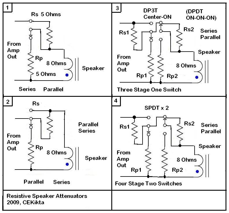
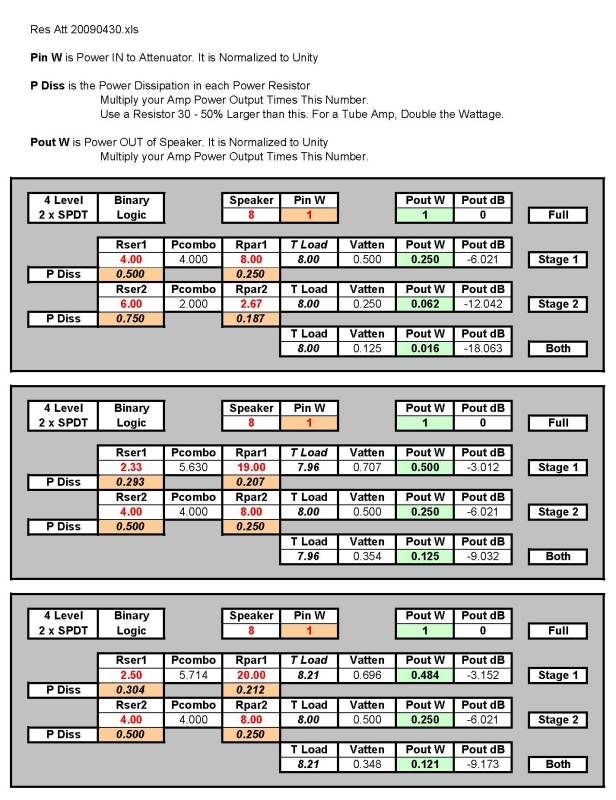
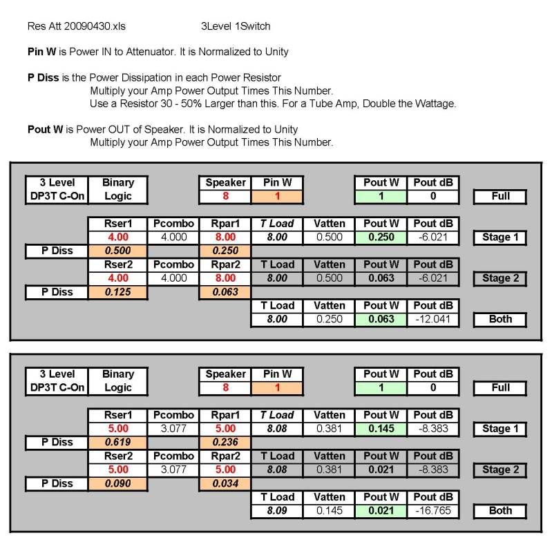
tedfixxIt's actually fairly easy to design a switchable attenuator. In its simplest form, it's two resistors and a SPDT switch. The exact same circuit works for a series first or parallel first topology. Only where you connect the speaker and the input swap between the two. Wow, duality strikes again. #1 is a series resistor first module and #2 is a parallel resistor first module. This leads to two designs; the first one with two switches that gives four settings, and one with a DP3T Center-ON (DPDT ON-ON-ON) switch that gives three. #3 is a 3-Level 1-Switch unit and #4 is a 4-Level 2-Switch unit. I'm sure that other variations and optimizations are possible, but I bore easily (and the VG awaits). I suspect that full-power, 1/4 power (-6dB), 1/16 power (-12dB), and 1/64 power (-18dB) might be more than enough. The Carr Mercury does this, it has 8 W, 2 W, 1/2 W, and 1/10 W. For a 60 Watt amp this is 60 W, 15 W, 3.75 W, and 7/8 W. The bottom view is shown for the switches.  Here are some values for a 4-Level 2-Switch unit. This does full, one stage, the other stage, and both. The first one reduces the power by 1/4 in each of three levels below full power. The second one reduces the power by 1/2 in each of three levels below full power. The third one has some easier resistor values.  Here are some values for a 3-Level 1-Switch unit. This does full, one stage, and both. The first one reduces the power by 1/4 in each of two levels below full power. The second one reduces the power by 1/7 in each of two levels below full power. It uses equal value resistors (because I could). 
|
|