oni
Rookie Solder Flinger

Posts: 14 
Likes: 0
|
Post by oni on Jul 2, 2009 14:17:02 GMT -5
Hello all, I am attempting to do ChrisK's version of the Mike Richardson mod guitarnuts2.proboards.com/index.cgi?board=schem&action=display&thread=3140, but with some small changes: 1. Bridge Tone Push-Pull Pot coil-cuts Neck and Bridge (instead of phase reversal) 2. Volume Pot in center 3. No ground loops Here's a diagram of my progress, apologies to ChrisK for making his schematic very ugly. All wire colors are exactly as they are on my guitar, in case digital photos are needed for clarification. Pickups are GFS Humbuckers: Green is hot, Black is signal ground. 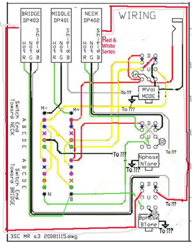 I'm stuck where to put my shields and neg. My cavity is covered in aluminum, but I'm confused on where to put the leads. Can I screw in a washer near the tremolo bar and solder all shields and signal grounds to that? Or do I need to make two contact points on the foil? Please let me know. And if there's any other problem with my wiring I'd be very appreciative if someone could point it out and give some tips on how to fix it. Thank you! |
|
|
|
Post by newey on Jul 2, 2009 20:33:30 GMT -5
Oni-
It's been awhile- welcome back!
You can do that, but it may be somewhat difficult to take it apart again, since you'll have all those wires running to a washer, screwed into the cavity. Unless you leave really long leads on all those wires, it's going to be tough to get a screwdriver in there to undo it.
JA's original star-grounding scheme has all these going to a "floating" ring terminal (which could just as well be a washer), and then a single wire from there to the cavity shielding. The ground washer or lug has to be insulated with electrical tape to avoid it contacting any other connections.
The single wire from the ground lug or washer means only one wire to desolder (or cut) to take the guard off again, plus the jack wires of course.
As far as your wiring diagram goes, am I correct that this is to simultaneously cut a coil from both bridge and neck HBs in the up position?
|
|
|
|
Post by ChrisK on Jul 2, 2009 22:19:41 GMT -5
You indicate what you want to do, but I can't make sense out of your diagram.
Troubleshooting it will require significant comparison with my original, for which I will not take the time to do.
It might be better to start with my diagram, review what it does, and discuss the incremental changes desired.
Converting the bridge pp tone pot to a dual humbucker coil shorting operation is easy. However, it may require some care since you are still reversing the phase of the neck pickup and still may care about inter-pickup phasing.
I don't understand the comment about ground loops; it appears that you are going to create them. The shield is a shield, not a signal conductor. It should be grounded at one point to the volume pot backshell. The rest of the grounding worked fine in my implementation. Since I did not do the isolation cap, I connected all signal grounds (and pot backshells) to the volume pot backshell. I did not rely on the shield for signal connections.
I did it the way that Fender does it in all modern Strats.
|
|
oni
Rookie Solder Flinger

Posts: 14 
Likes: 0
|
Post by oni on Jul 3, 2009 0:37:59 GMT -5
Thanks, I'm glad to be back. It seems my diagram makes things more confusing, opposite of what I was going for  But this is progress, thanks. I'll tackle this step by step. First, the only wiring I changed from the original (neglecting that all my grounds and shields are now disconnected) is to the Bridge Tone Push-Pull Pot. Here's the set-up: I have the 'series link" (red & white wires) from the neck and bridge humbuckers going to the central poles of the push-pull on opposing sides. I moved the capacitor to the wiper, grounded to the pot's shell. The hot wire from the bridge pickup is wired to the the Bridge connector on the superswitch. That Bridge connector is then connected to the "high" end of the pot. My confusion is that while this is generally how coil-cuts are set-up, I don't understand well how the super-switch functions in this circuit. Is the wiring from the B pole on the switch practically routed to the + input on the volume pot? If so I would think I wired it correctly... Another confusion is I don't understand why the tone capacitors in the original are wired to the push-pull switches and not the pot's wiper... I'll leave the grounding questions for later, but the aluminum lining is already set as per the "Quieting the Beast" instructions, which is why I removed the connections between the pots' shells... EDIT: after seeing the thread "The "Blocking" Capacitor", I now understand how these aren't ground loops as JA suggests, no need to explain |
|
oni
Rookie Solder Flinger

Posts: 14 
Likes: 0
|
Post by oni on Jul 4, 2009 1:46:41 GMT -5
Here's a clearer picture of the Bridge tone with comparisons to the original. Would these work as drawn? 1. My current wiring for coil-cutting the bridge and neck that removes the phasing on the bridge. 2. An alternate option for only coil-cutting the bridge using the pot as a "spin-a-split" - removes the tone control capability but (should) retain the phasing. 3. Original  |
|
|
|
Post by ChrisK on Jul 5, 2009 1:01:45 GMT -5
Let's take the approach that the same things are happening as my circuit - almost.
1. The bridge phase pp switch will become a dual-channel intra-pickup series coil humbucker coil shorter. We're going to short a coil in both humbuckers to get a single coil sound. We're going to keep in mind that we might want to use a 0.022 to 0.047 uF cap to short across each coil to be determined later (this can give a nicer single coil sound with some hum cancellation intact). As a result, we're not going to pre-bury the connections from the pp switch.
Remove the wiring from the bridge pp switch and wire the bridge pickup to the tone pot/cap as if the switch isn't being used (the connection positions when the pot is down).
2. Now "Sparky", let's not get carried away in the moot direction. There is a post in the module section of "Electronics and Wiring" that relates to the Red Rhodes tone control coil short mod. You will see similar themes in my "Free Neck On Switch" post. The point is that Peavey used Red's patent (long expired) to shunt (a kind word for short) one coil on an intra-pickup series coil humbucker. As the tone is turned from "7" down to "0", it works like a normal high-cut tone control. As the tone is turned from "7" to ""10" it shunts one coil, giving an enhanced single coil sound. This tone control goes to "13".
As I show, an extra cap can be used as well.
3. Now, my tone circuits may be confusing because they are across the respective pickup and not across the places convenient in worlds parallel only, lost in knowledge past to the plumbers present blind.
A series RC tone high-cut circuit is a two terminal network. They're across the bridge and neck pickups respectively to give the option of capacitive shunting across those pickups when structured in inter-pickup series (the whole point to the MR scheme).
Forget aaalllll about ground until you understand the modules first.
Summary:
We need to replace the bridge and neck pickups with your pickups. There is a center-tap between the series coils that we will do something with.
We may actually use that there third terminal on the tone pots for something useful (resistive/RC coil shunting).
When we "see" the force (well, the signal flow), we'll get Luke back on the ground.
|
|
oni
Rookie Solder Flinger

Posts: 14 
Likes: 0
|
Post by oni on Jul 5, 2009 8:07:48 GMT -5
Your words look like greek (poetry) to me, but after reading it a few times I'm guessing you meant what I've drawn below? 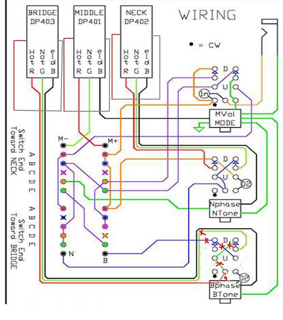 If so, we have nothing but a tone control for the bridge at this point, correct? |
|
|
|
Post by newey on Jul 5, 2009 8:46:52 GMT -5
Correct- but you now have the starting point for wiring the push/pull to do what you want it to.
ChrisK's post is a bit elliptic because he's trying to get you to think this through. He also has suggested a few places here to look for additional help.
He has also answered your previous question about the tone caps.
You have some decisions to make about whether you will use the tone control as suggested or not, and whether you will use the cap as suggested.
You are now at the point where the p/p can be thought of as a module which will "sit" at a certain point in the signal path.
|
|
|
|
Post by ChrisK on Jul 5, 2009 23:41:05 GMT -5
tedfixxNo. You did go back to the beginning, but moved on without seeing. 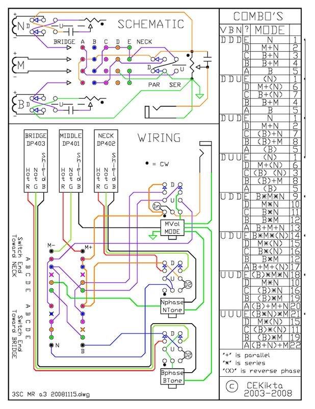 The bridge red wire ( hot) originally went thru the pp phase switch to the blue wire going to the "B" terminal on the 4P5T lever switch. It also connects to the bridge tone cap. Connect the bridge red wire ( hot) to the blue wire going to the "B" terminal on the 4P5T lever switch. Also connect it to the bridge tone cap. You can use the tone cap with insulated leads (hint) as the jumper from the "B" terminal to the pot terminal. The bridge green wire ( not) originally went thru the pp phase switch to the green wire going to the "wiper" terminal on the bridge tone pot. It also connects to the signal ground since the bridge pickup structure is ground referenced. The bridge green wire ( not) now goes to the "wiper" terminal on the bridge tone pot. It also connects to the signal ground. After doing these steps the bridge pp switch will not have any wires attached to it (freedom is). You will also note that each tone pot has an unconnected terminal with a dot next to it. Said dot indicates the CW direction of rotation. When the pot shaft is fully Clock-Wise, the wiper has a very low ohmic connection to said terminal. Said terminal either directly, or thru a 0.022 uF series capacitor (a good place to start) can be used to short an intra-pickup series coil. i37.photobucket.com/albums/e84/cekikta/Wiring/Modules/RedRhodesTone_CoilSplitPotD.jpgA clever sort might see how to use the same cap for both the high-cut tone function (toward CCW) and the coil shorting function (toward CW). 
|
|
oni
Rookie Solder Flinger

Posts: 14 
Likes: 0
|
Post by oni on Jul 7, 2009 6:08:49 GMT -5
If both the red, hot wire and cap are going to the same place, I figure the blue is no longer needed. Also not sure about the "insulated leads" unless you mean any insulated wire could do. I don't have any heat-shrink tubing to attach to the two stems of the capacitor... But other than that, my new set-up hopefully will be in-line with your instructions... 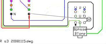 I got the feeling that having any unused lugs was a sin around here ;D My confusion now stems from the fact that the capacitor's path to ground is opposite from what I'm used to seeing. It seems that the wiper brings it into ground, instead of the POS being wiped into ground. I suppose it still works, but why would the NEG not also be connected to the POS? This causes no problems, since it's only the high frequencies of the POS mingling with the NEG? Even if so, if I route the series link directly to the opposite lug, it will certainly blend into the NEG signal when rotated CW. That causes no problems? 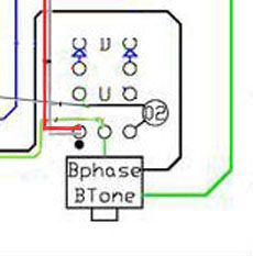 and if the capacitor is put in the middle, it seems that the series link has no path to ground... 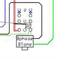 it escapes me how to possibly do it with only 1 capacitor without using the pp... are we going to use the free lug on the neck tone? |
|
|
|
Post by ChrisK on Jul 9, 2009 23:08:57 GMT -5
Do you want to try the variable shunting with the tone pots (which will not have tone cut for the respective pickup when the one coil is shunted on that pickup), or do you want to try the pp switch shunting both first?
|
|
oni
Rookie Solder Flinger

Posts: 14 
Likes: 0
|
Post by oni on Jul 10, 2009 0:48:56 GMT -5
If I still have tone control while it is humbucking ( 0-8 on a logarithmic pot was it? ), I'd rather go for the variable shunting on the Neck and Bridge pots so I can save that pp switch for an HH guitar I have. I intend to use the single coils when I need the extra treble, so cutting their high frequencies would also be self-defeating  Also working on what the possible combinations could (I want to) be. This seems about right but only my first draft. 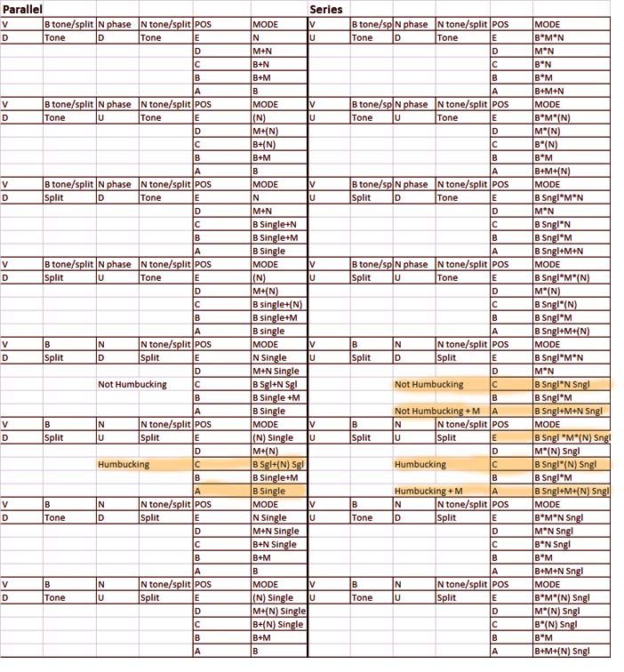 |
|
|
|
Post by ChrisK on Jul 10, 2009 20:52:19 GMT -5
Assumptions
Green is HOT
Black is NOT
Bare is shield
RED and WHITE are tied together as the series coil tap.
When a series pickup structure has one coil shorted, does the RED and WHITE connection go to the Green (HOT) or the Black (NOT)?
Are the bridge and neck pickups identical? Which coil pairs will be hum canceling? Should the RED and WHITE connection on one go to the Green and to the Black on the other?
|
|
oni
Rookie Solder Flinger

Posts: 14 
Likes: 0
|
Post by oni on Jul 11, 2009 2:50:46 GMT -5
The wiring is identical between pickups. The wiring code is the same, color-wise, but opposite polarity from Seymour Duncans:
North Start: Black -
North End: White
South Start: Green +
South End: Red
The main differences are that the neck and mid are rail-type humbuckers that fit in the single-coil slots, and had (before I separated them) the shield and signal ground connected.
The resistances are also different:
Neck ~ 6k Middle ~ 10k Bridge ~ 14.5k
Honestly, I think the neck will be too weak split by itself, but I am interested in the Bridge/Neck combo.
I'm assuming that the coils will split the same way (N or S) and will be in-phase/not hum canceling when split. But, with the phase pp switch on the neck, I can make them OoP and hum-canceling.
But, I will ask to make sure. If my assumption is correct though, I'm guessing I would just need to wire the red/white to the respective CW lug?
|
|
|
|
Post by ChrisK on Jul 11, 2009 23:11:27 GMT -5
Yes!
|
|