|
|
Post by ozboomer on Jul 21, 2010 2:23:21 GMT -5
I thought I'd just update the diagram with a pictorial "explanation" of how the DPDT on-on-on switch actually works, together with our local "switching convention" (that is, up=off, down=on), viz: I also modified the terminal labelling to better match the "1st switch = left, next switch = right" arrangement on the page. I'm pretty sure this is right, so I think I'll forge ahead and get onto updating the schematics for the 2 modules... John |
|
|
|
Post by newey on Jul 21, 2010 6:11:18 GMT -5
Oz- Your schematic representation of the DPDT On-On-On switch is good- better than most. However, your notation "n/c" is a bit confusing. This usually means "normally closed" in the world of switch nomenclature, which isn't the case with this switch. My schematics software doesn't have a diagram for this type of switch, just the standard DPDT symbol, which can be used, but which leave one to "imagine" the center position and its internal connections. Yours, at least, shows the center connections. NKK and Honeywell, respectively, use the following schematics for this switch in their product literature. Neither of these is any better. 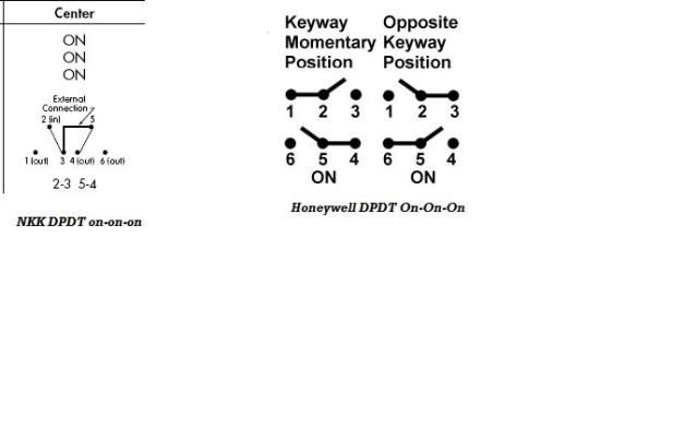 Note that the NKK version specifies an "external connection". Apparently, if one orders a SPDT On-On-On, they ship the DPDT version with instructions to make that external connection. The Honeywell version is used for the momentary versions of the switch as well as the one at issue here, leading to further confusion. Anyone have a better schematic symbol for this switch? |
|
|
|
Post by ozboomer on Jul 21, 2010 6:57:48 GMT -5
...your notation "n/c" is a bit confusing. This usually means "normally closed" in the world of switch nomenclature, which isn't the case with this switch. That's easily fixed - I'll just write "OFF" 'coz in the context of the labelling, we're talking about an extra pickup being in series, in parallel or nothing = off. Thanks for the clues... |
|
|
|
Post by gumbo on Jul 21, 2010 7:55:54 GMT -5
You know you'll scare them with the "UP = OFF" thing.....  |
|
|
|
Post by JohnH on Jul 21, 2010 15:55:41 GMT -5
Anyone have a better schematic symbol for this switch? On a schamatic, I often just show an extra dotted line, representing where one of the poles is in the middle position.  But i think Oz'z way is fine too. Heres a version from DGB studios:  John |
|
|
|
Post by newey on Jul 21, 2010 23:26:27 GMT -5
The DGB one is the best of the bunch. Now if I can only figure how to import it into the library file of my schematic software . . .  |
|
|
|
Post by ozboomer on Jul 23, 2010 4:28:37 GMT -5
Just another update on the lil' circuit to add a pickup in parallel/series... I spent a few hours scratching my head, trying to come-up with a totally "isolated" version of the module but I was going bananas trying to come to grips with the weirdo wiring arrangements with the on/on/on DPDT, etc... So, I've made-do with something pretty close -- As long as the ground point of the "signal source" is accessible, I have something fairly usable, I think, viz: Anyway, back to tidying-up more modules for posting... |
|
|
|
Post by newey on Jul 23, 2010 5:12:56 GMT -5
HMM. Isn't PU2 disconnected in the center position, while the "signal source" is "on" in the center?
|
|
|
|
Post by ozboomer on Jul 23, 2010 6:35:35 GMT -5
HMM. Isn't PU2 disconnected in the center position, while the "signal source" is "on" in the center? Yup-yup... and that's by intention. A function of the module is to be "transparent" when the module switching is "OFF"; in that arrangement, the output of the circuit would be the same whether the module was included in the schematic or not. Here, we still have the ground of "signal source" going to ground and the output has nothing added to it, so I think that side of things is Ok. All this module should do is (optionally) add PU2 to the overall sound. The switching arrangement simply defines how the pickup is included (in series, prior to the "signal source"... or in parallel, with the output from PU2 being added to the "signal source" output). It also wants to do its switching so we don't have the heartache of a "hanging hot" on that pickup when it's not "in-circuit" as well. Granted, I might be missing something 'coz I've been peering at this thing for too long ... but I think the schematic as shown would work as I have described...? Fanx! for the thought... |
|
|
|
Post by newey on Jul 23, 2010 7:44:01 GMT -5
OK, I guess I was confused by your statement that this was "a parallel/ not connected/ series wiring that is generally applicable to any signal source", leading me to believe it was the signal source that would be not connected in the center position.
Obviously, either the pup or the signal source can be disconnected in the center position by simply switching the connections at b and f, (also thereby flopping the series/ parallel settings around as well.)
|
|
|
|
Post by ozboomer on Jul 31, 2010 23:32:38 GMT -5
I have a few things in the wind at present regarding SimpleMod.. not the least of which are the effects of my latest thinking over in the Designing Your (Next) Virtual Jazzmaster/Jaguar thread... In short, SimpleMod-b is working along Ok... but I have some thoughts I'm getting together for maybe another 5-10 mods, all along this line... including the use of clone P-90 pickups (well, P-94-like pickups, I guess), humbucker pickups and some fairly simple wiring and switching arrangements. More updates to follow, as I get to work (for the next 3 years, the way I get through these things!) John |
|
maxcalibur
Meter Reader 1st Class
 Half Bullet, Half Sword.
Posts: 57
Likes: 0
|
Post by maxcalibur on Aug 1, 2010 3:58:20 GMT -5
Does anyone have or can anyone put up diagrams like ozboomer's that display the switching functions of different, more complex switches (4PDT and 4PDT on-on-on variations maybe). I particularly like the ones showing the poles in red and blue.
It would be really handy for anyone trying to design their own more complex circuits, like this one was for more designing my relatively uncomplex one!
|
|
|
|
Post by ozboomer on Aug 1, 2010 5:09:21 GMT -5
Does anyone have or can anyone put up diagrams like ozboomer's that display the switching functions of different, more complex switches (4PDT and 4PDT on-on-on variations maybe). A good starting point is the Electronics Templates thread, right here on GuitarNutz2. ...and if you don't mind dealing with Spanish (of which, I know nothing!), Hemertico Guitar provides some useful diagrams.... I thought I saw my diagram somewhere a'fores... |
|
maxcalibur
Meter Reader 1st Class
Half Bullet, Half Sword.
Posts: 57
Likes: 0
|
Post by maxcalibur on Aug 3, 2010 11:52:17 GMT -5
Thanks, I'm having a look at them at the moment. I want to switch two circuits in unison (one active, one passive) but now I'm looking at using two switches and connecting them mechanically. Still handy to know where all those diagrams are!
|
|
|
|
Post by ozboomer on Aug 20, 2010 21:06:01 GMT -5
...and so SimpleMod-c begins. Well, not so much a new design as it's an application, I guess. I lashed-out on (another) loaded pickguard but in an HSS configuration this time. I haven't done anything with humbuckers up-to-date, so I thought I'd have a go with one of these:- Sidebar: I've mosaiced-out (another new word) the supplier branding on these photos, as I expect that's the right thing to do!? Continuing... However, upon receiving the pickguard, and checking the wiring I've become a little confused... Here's a schematic I've derived from a tight examination of the wiring:- My questions: - Why is there a wire between the two tone controls? Other than providing some parallel combination thing (0.033 + 0.033 = 0.066 uF), I can't see the point!? Here's a detailed photo:-
- I was wondering about the way the humbucker is wired into the circuit. Now, I don't know if my "A+", "B-", etc are correct in my schematic but the colours of the wires and where they're connected are pretty right... but I still can't see what the point of the wiring to the other half of the 5-way is...!? ...unless there's something to do with phasing or something in the M+B position, maybe? Another detailed photo:-
Anyway, I think the circuit will still work but I'm still not sure if it's wired-up properly? ...and I certainly don't fully understand what's going on with it... Maybe someone could shine some light on it for me, please?! John |
|
|
|
Post by JohnH on Aug 20, 2010 22:05:23 GMT -5
It does look like they added two caps togther to make a single bigger cap. But if you remove the link wire, then both tones will get 0.033 instead of 0.066uF shared. Thh wiring seems like normal Strat, with the bridge shunted to a single coil when combined with the middle
So where di you get it?
John
|
|
|
|
Post by ozboomer on Aug 20, 2010 23:31:11 GMT -5
Thanks for your thoughts, John... It does look like they added two caps togther to make a single bigger cap. But if you remove the link wire, then both tones will get 0.033 instead of 0.066uF shared. Ya, that's what I thought. I guess one of the first mods to be made will be to drop the "link wire" and change the caps... and maybe move the neck tone to the bridge or sumfin'... Okie, I think I can see that... As I said, I guess it'll work, so I might as well put it in then, eh? I bought the loaded pickguard from Dragonfire Guitars/Guitars Online/TNT Guitars (how many names can one business have!?) I've read both good and bad about the pickups from these people... but for ~US$40 for the pickups, electronics, pickguard and all wired for me, I'm not whining too much...! ...and I'm mainly about trying to come to grips with the wiring and sounds of a humbucker in a Strat (my old '74 Les Paul copy had some Ibanez something-or-others installed back in '78 or thereabouts.. and I have/had a reasonable idea of the humbucker sound in THAT guitar). The pickups in this pickguard are ceramic (neck, middle) and the humbucker is one of their "Black Screamer" pickups. Actually, my development with pickups in my Squier Bullet Strat has followed this sort of route: - the original, as-supplied ceramic single coils
- cheapo, probably ceramic single coils (eBay)
- Squier 'standard' (MII) pickups (we guessed - more details)
- more ceramic types.. but with a humbucker
...and I tend to like the ceramics... but one of the options to come in an upcoming SimpleMod is to install some Fender Tex-Mex pickups, which I've seen running cheap-ish (~US$80 for the set of 3) at a few of the on-line stores in recent months... or some GFS versions... at least, that's the plan, anyway. ...but that's after I fiddle with the humbucker I have here now... together with some experiments with a GFS Dream 90 which is also on its way... Like I said - a stack more projects in the wings... John |
|
|
|
Post by ozboomer on Aug 22, 2010 4:58:55 GMT -5
Now, I know it's very early days... ...but I've installed the loaded pickguard today and I've had a bit of a play... and it's more-or-less what I expected, which is good and bad, really... all within the context of what's important to ME and not your normal "guitar player in a band"... Some initial notes: - The tone controls don't do too much; they cut the highs out quite alright but it's the old problem of only making their changes when the pot is turning through 2 down through 1 -- to me, the taper on the pot isn't right... but the combined 0.033uF cap. values seem to cut the highs to a reasonable degree of "mellowness", so that's not too bad.
- The volume control runs pretty smoothly but the other known problem of the sound being dull at lower volumes is in there... but we know how to make that work better.
- Combining the single coil pickups work and sound as expected. Actually, I quite like the sounds of these single coil pickups when used alone or combined (with another single coil)... BUT I don't know about the combination with the humbucker.
Remember that the 5-way has some weirdo wiring such that only one coil from the humbucker will be combined with the middle pickup when the 5-way is in the "M+B" position. It certainly doesn't have the "quack" that I like and if anything, the sound is kind-of muddy or indistinct. This validates what has been written in many places previously that combining a single coil with "half a humbucker" doesn't sound as good as a single coil + single coil combination.
- The humbucker/bridge position is what you'd expect and does its job pretty well, I think, sounding good and bright, significantly louder and is very quiet (it IS a humbucker, after all)... but personally, I really don't like the sound. The specs say the humbucker is rated at 16.9k while the single coils are rated at 6k, so you'd expect the difference in volume and such... and if you're in a band and you take your solo, you'd want some grunt as you flick your guitar into bridge position...
...but for the way I play, the environment in which I play and the sort of music I like and so on, I don't think this massive change in volume is suitable -- I'd rather maintain a relatively similar level and let ME change the volume as I want. If I have a wiring scheme installed where I use a series switching of "similar rated" single coils... or even if I use them with a blender, I think those arrangements would suit me better...
To repeat, we're still early days with this arrangement... and I'll play with this pickguard installed for a while and we'll see how it goes... but I'm thinking this layout might not be for me this time... Oh well... As far as the actual loaded pickguard is concerned, I reckon it's not too bad... and I admit I don't really have a very sophisticated ear for the sounds of pickups (yet)... but for around US$40, I reckon it's not a bad way to go in terms of a cheap upgrade to a Strat-style guitar. In any event, I hope to get around to recording some of my standard comparison sounds during the week so you can hear some of the differences compared to the earlier SimpleMod versions. Not a complete success but still a worthwhile exercise, SimpleMod-c... and it gives me something sort-of different to play around with while I work on SimpleMod-d  John |
|
|
|
Post by gumbo on Aug 22, 2010 6:53:07 GMT -5
...hmmm... ..soundz a lot like my ol' Chinese Strat..bought years ago in a local pawnshop...it's been propping up a corner of the room for a few years now, and doesn't actually see the light of day .. that said, it was a good little axe and served its purpose at the time. ..it was only when I moved away from those pickups and that guitar that I realised(sp) some of those tonal limitations....these days playing 'real' Strats and Teles, it's not something I wish to return to.. ..if ever I get the time and inclination to gut it and use it as the (planned!) testbed for other stuff, I'll mail you the old loaded pickguard...I'm sure you'll love it...  ...at least it'll keep your mind off the election  |
|
|
|
Post by ozboomer on Aug 22, 2010 7:24:40 GMT -5
..if ever I get the time and inclination to gut it and use it as the (planned!) testbed for other stuff, I'll mail you the old loaded pickguard...I'm sure you'll love it... Well, you'd be excused for thinking I'm collecting pickups/pickguards as a side-hobby... The current count is 9 single coil pups and 5 pickguards not in guitars at the moment...(!) *cof* ...Uhrm... Ya.  |
|
|
|
Post by ozboomer on Aug 24, 2010 6:56:26 GMT -5
In preparation for an upcoming Strat mod, I've been trying to develop some sort of single-pot -based tone control that offers a bit more than the standard "treble cut" tone control. Y'see, I'm looking at using the 3 standard Strat pots but they'll have the functions of a volume control, a tone control and a blender in this mod; ...and this is why I'm looking at having only a single-pot tone control. The cavity under the pickguard doesn't have a lot of room (only ~3/4" or ~19mm) so I can't really consider any dual-gang or push-pull switch -type arrangements on the tone control either. One thing I'm contemplating is to try a well-used midrange control. Often used in an Esquire guitar, I understand, this tone control uses one pot and either boosts the midrange (well, it sounds like that - it actually cuts the low and high frequencies) or cuts the midrange (directly). A starting point for the design might be: ...where the "minimally altered" sound appears when the control is on "5". As the knob is turned 5->10 (clockwise), the midrange is "boosted" (see above), whilst the midrange is "cut" when the knob is turned from 5->0 (anti-clockwise). The most critical things with this design, then, appear to be the values of the RC and RLC components to determine the cutoff frequencies... and I expect I'll need to experiment some to get a handle on those limiting values. I'd be interested to know if anyone has gone down this path before and if you have any suggestions on how I might proceed in my testing. Is it, in fact, "good enough"(?) to only have a single midrange tone control on the guitar (given I'll be using a blender to combine the pickups)? ...or should I simply stick with the conventional "treble cut"-style tone control? From prior experience, it appears an inductor can be quite a pain to use or at least accommodate in the guitar cavity in various situations. Therefore, I wonder if a "choke" (like this one that is available locally) would be suitable to be used in this application? ...or, because the frequency of that choke is WAY too huge, maybe I should just work out some means of mounting a small audio transformer (like this one) somewhere to use as in inductor..? I'd appreciate any thoughts or suggestions, as always... John |
|
|
|
Post by ozboomer on Aug 29, 2010 6:19:17 GMT -5
I finally got around to recording something basic so you can hear how the loaded pickguard sounds. Nothing flash.. but you can do some sort of comparison of the latest SimpleMod versions:- More news shortly... |
|
|
|
Post by ozboomer on Aug 29, 2010 6:31:38 GMT -5
I recently had a go at (re-)building a couple of the passive tone controls I've mentioned throughout this current thread... and the short version is either my soldering is still a bit ordinary OR the designs just don't do anything very much (as I originally determined with the breadboard versions)... Without going through all the detail, I think I'll just use a simple "treble cut" (standard) tone control for a later version of SimpleMod, where I can only use one tone pot -- as always, go with the simplest idea when testing things out, I think... SimpleMod-d has now more-or-less been designed.. and I'm currently working on the wiring ("hook-up") diagram. TheRealWorld TM is kinda hectic at present, so it'll probably be a lil' while before I post anything about the design... let alone getting around to building it... but I'll get things on here as soon as I can... John |
|
|
|
Post by ozboomer on Sept 17, 2010 8:00:14 GMT -5
Some details about the next step in the experimentation: SimpleMod-dThis time, I've been looking at the switching arrangements in a bit of detail, with a view to what features I want in later SimpleMod versions. This version allows us to turn-off the middle pickup entirely, so we'll only switch the bridge and neck pickups (with a 3-way switch)... as well as being able to add the middle pickup at any time in parallel OR series with the bridge and neck pickup combinations. Note that I've retained the tone and volume controls from SimpleMod-b and have just modified the switching options - this will simplify the wiring required. So, to the obligatory diagrams (left-click the small pictures for larger images - and apologies for the slightly distorted larger images)... The Design (1024x430, 52kB) :The Wiring Diagram (1024x724, 68kB) :Pickup Combinations: | 3-Way | Mid-Par. | Mid-Off | Mid-Ser. | | 1. | B+M | B | B*M | | 2. | (B+N)+M | (B+N) | (B+N)*M | | 3. | N+M | N | N*M |
...with + = parallel and * = series... and: ... the traditional (5-way switch) sounds (M alone is not available) ... extra sounds from SimpleMod-b... additional sounds with this modI intend to start wiring in the next week or two... so DO let me know if you have any thoughts, etc... Fanx! John PS ... SimpleMod-e will be a development of the H-S-S arrangement that is currently installed in my Bullet; it's effectively a separate, parallel path of experimentation... |
|
|
|
Post by JohnH on Sept 17, 2010 8:29:10 GMT -5
Hi John - I think you may have a winner there! I'll take another look in the morning
John
EDIT: Yes it does look like you will get a good range of sounds there. Schematic looks fine to me. On the wiring diagram, it could do with a bare wire to link up the back of the three pots.
If you are interested in getting a few more sounds, and a more interesting tone control (the Red Rhodes tone control) in series mode, you can add a wire from SW2B-b to the unused tone pot lug. Its as I have posted elsewhere, in series mode, at max treble, you get more single coil treble with series bass, as the M pup is bypassed with the tone cap.
I see you like to use a small tone cap, though for this bypass function a larger one may sound better. You might not want to mess with your design, which is good as it is, but if this is of interest, you can put the centre tone lug to ground, put the small tone cap that you like on the upper lug, and a larger one on the lower lug to go to SW2B. None of that affects anything but the series setting.
cheers
John
|
|
|
|
Post by ozboomer on Sept 17, 2010 20:31:45 GMT -5
Well, I had a look around GNutz2 and elsewhere for some help with this... but couldn't find anything (directly) helpful... so perhaps someone can help save my mind... Before I try and wire things up in a "weird" way, I want to find out how to wire-up a 3-way switch the "conventional" way, with 3 single coil pickups. My meter tells me the following: for the aftermarket 3-way switch I have, viz:-  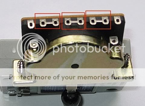 ...I get the following:- Position 1 (lever towards the "8", as shown): pins 1, 4, 5, 6, and 7 are connected Position 2 (centre): pins 2, 3, 4, 5, 6, and 7 are connected Position 3 (lever towards the "1"): pins 2, 3, 4, 5 and 8 are connected Now, I could almost get it to work if I consider pins 4 & 5 as the "commons"... and pins 2 & 3 weren't connected, similarly for pins 6 & 7... but as the connections are now, I can't see how I can wire it up so that Pos 1 = Bridge, Pos 2 = Middle and Pos 3 = Neck. I would really appreciate it if someone could provide some clues on how this switch needs to be wired... as I slowly go bananas ... Edit: added an additional photo showing the joined pins that are still joined (internally) when the 'bridges' are cut |
|
|
|
Post by ozboomer on Sept 17, 2010 20:55:28 GMT -5
...On the wiring diagram, it could do with a bare wire to link up the back of the three pots. Yup, I was thinking about that already, as I already have had some grounding issues with SimpleMod-b... maybe I'll just draw a single line across the back of the pots... hmm... Oooo, Fanx! for that lil' clue... an interesting idea for sure. Uhrmm... and I assume you mean the "treble cut" tone pot? At any rate, I'll take a note of this and revisit it when I get down the track a bit; one of the options to come (depending on how the "switched" series-connected middle pickup sounds), is to go back to using a blender pot (in series mode) for the middle pickup... but that would mean I'm going back to a single tone control pot... and that's where this idea might be useful... I think  I still have to properly suss-out the workings of what you've described... and it will break-up the modularity of the design a bit... Hmm... Fanx! again for the handy thoughts... |
|
|
|
Post by newey on Sept 17, 2010 21:36:01 GMT -5
Oz-
Doesn't sound like a standard Fender-style 3-way switch, imported or otherwise. Do you know whence this switch came?
Ibanez makes some "dedicated" lever switches that are internally connected for a preset wiring scheme; there are other such "dedicated" switches around as well. Do you see visible jumpers between 4 and 5, as well as 2-3 and 6-7?
The usual import switch comes with 4 and 5 jumpered together with a piece of wire, easily desoldered. I've never seen one with any other lugs pre-connected like that.
Sometimes with these wafer-ish switches, one can make out the internal connections through the wafer.
|
|
|
|
Post by JohnH on Sept 17, 2010 22:02:29 GMT -5
I can’t quite picture what that switch was intended for, but I believe it can be used to suit your purpose.
4/5 seem to be connected as the poles – so they can go to the hot output (different to your schematic)
Let’s say as shown in the photo, the lever is at the No. 8 end, and that is installed so it is towards the bridge pickup
Bridge pickup should go to 6 and/or 7
Neck pickup should go to 2 and/or 3
That should give you position 1, B to output, position 2 both to output, position 3 N to output
John
|
|
|
|
Post by ashcatlt on Sept 17, 2010 22:15:25 GMT -5
It's Standard Tele wiring, and works fine for the diagram in reply 143. Reply 145 seems to be asking for Original Strat wiring: Neck - Middle (NOT N+B) - Bridge ( ) If this switch is internally wired with jumpers it ain't gonna do the Strat thing. Not without breaking it open, anyway. On a side note, I can't see any reason you would need to jumper switch 2B's Off lug to it's Series lug. In Off position it goes nowhere either way.Sorry, 2B's an on-on-on, the jumpers are internal and there isn't actually any "Off Lug"! |
|


 I still have to properly suss-out the workings of what you've described... and it will break-up the modularity of the design a bit... Hmm...
