|
|
Post by ozboomer on Jun 29, 2010 6:03:58 GMT -5
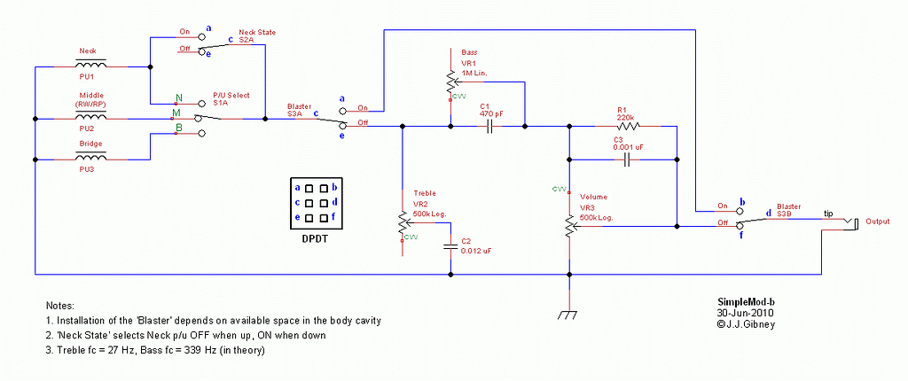
Here's another simple addition/modification scheme that I'm about to assemble this weekend (I hope). Now, there's no doubt fiddling about with pickup combinations and all sorts of unusual sounds is great to experiment with... but as a wise man recently suggested to me, I thought I'd just try for a simple change or two this time around. Depending on your point of view, the standard Stratocaster wiring has a number of problems/non-features that really need to be addressed. Some of these include: - the sound gets duller when the volume is reduced;
- the way the sounds change (in tone and volume) are not necessarily correct. Again, depending on your point of view, the pots installed for the volume and tone controls are often of the incorrect type, and I've found that you need to try both LINEAR taper and LOG taper pots in your guitar to see which types sound best to you; and
- the only control of the tone is through the use of "treble cut" controls and they interact in a (kind-of) non-intuitive way.
The primary objective of this version of "SimpleMod" is to address these issues... and o'course, I have to include SOME alternate sounds  - so in this design, I've also included: - a "neck on" switch, which will provide the "missing" sounds of B+N and B+M+N; and
- a "blaster" switch, so that the tone and volume controls can be bypassed, providing the sound of the pickups *only* at the output of the guitar.
Now, let's look at those "issues"... - the tone changes with volume can be alleviated by use of the Treble Bleed Mod;
- some better control of overall tone can be achieved by use of the "Sumgai Tone Control" (for want of a better term) - it's basically a combination of a standard "treble cut" pot and a "bass cut" pot - and these controls always apply to the total sound coming from the guitar.
So, to some pictures (left-click the small pictures for larger images - and apologies for the slightly distorted larger images)... The Design (1024x423, 20kB) :The Wiring Diagram (1024x724, 68kB) :Pickup Combinations: | 5-Way | Neck Off | Neck On | | 1. | B | B+N* | | 2. | B+M | B+M+N* | | 3. | M | M+N | | 4. | M+N | M+N | | 5. | N | N |
...where the "*" indicates the traditionally "missing" sounds. So, have a look at it, see if you can find anything wrong and DO let me know what you think. Otherwise, I'm getting out the soldering iron on the weekend  Thanks, folks. John |
|
|
|
Post by JohnH on Jun 29, 2010 7:15:13 GMT -5
I think it is good, and well presented too. My only thought is about the 1M volume pot, which together with the 150k on the treble bleed may make it hard to turn down. My favorite recipe is 500k pot and 220k resistor. Im also have used 1nf for the treble bleed cap, and am thinking I might try a bit less next time, maybe 680 or 820 pF, since i usually use short cords.
John
|
|
|
|
Post by ozboomer on Jun 29, 2010 8:02:53 GMT -5
I think it is good, and well presented too. Fanx! It's taking me a while but I'm slowly learning TheGuitarNutsWay(tm) of how we present things here Okie, then. I won't change anything in the diagram for now (I'll wait for the schematic posting after I've installed/built it) but I'll have a go with (1nf+220k), I think. I've tried (1nf+150k) on a 250k pot and it works pretty well for my ears... In my recent testing, I tried both a 500k pot and a 1M pot for the volume control and didn't really notice much difference tone-wise (I didn't test with a treble bleed - I was just listening for any changes with the volume pot in-circuit). The annotations begin........ |
|
|
|
Post by sumgai on Jun 29, 2010 17:39:48 GMT -5
John #2,
Sorry, I can't pass this one - it's back to the drawing board for you.
Look at the Treble Control - you've got one of the three terminals connected to ground. In effect, this means that:
a) The Tone control is now fully in parallel with the Volume control, at all times. Assuming that both pots are the same value, that cuts the resistance across the pickup in half, which translates to it being loaded down even more with Major Tone Suck. Bears re-thinking.
b) Instead of having just an R*C circuit to cut the treble, you've now got an R1*(R2+C) circuit. Since both R's are always variable, the resulting response curve will become Mr. Murphy's playground, to be sure. Bears re-thinking.
Otherwise, the rest of it looks good to me.
HTH
sumgai
|
|
|
|
Post by ashcatlt on Jun 29, 2010 17:53:25 GMT -5
On the other hand, we have had indications in the past that the bass cut control can work much better if it has one end grounded, acting almost like a volume control with a treble-bleed cap.
|
|
|
|
Post by JohnH on Jun 29, 2010 18:33:25 GMT -5
I think johns tone circuit is OK, subject to the actual values which I believe he has chosen by testing. On the treble cut control, I found that whether or not the third pot lug is grounded makes no significant difference, and one of my guitars actually came that way stock
J
|
|
|
|
Post by ozboomer on Jun 29, 2010 21:52:59 GMT -5
My dear sumgai... Sorry, I can't pass this one - it's back to the drawing board for you. Look at the Treble Control - you've got one of the three terminals connected to ground. Rats. Quite right you are. That's an error in re-drawing the schematic and it's flowed onto the wiring diagram. My actual testing rig doesn't have the connection to ground from the VR2-CW lug, so I'd better fix those drawings up... I'll do that later today. It always helps to have another set of eyes run over these things, obviously  So, Fanx! for highlighting the trouble...! Trivia: The external testing rig (that is a constructed "Sumgai Tone Control", including mis-labelled knobs!): I liked the sorts of sounds that were coming through the box after I maxed-out the on-guitar controls (that is, minimum treble cut and maximum signal through the volume pot - remember, I still have SimpleMod-a without any pot+inductor running in this guitar) ... This is partly why I want to include the "Blaster" thingy, so I can better ascertain what the "pickups only" sounds are really like. Maybe I'll record some sounds with the outboard box in place and then do the same after the re-wiring is done...? Anyway, thanks again for the checking, everyone. More later... John |
|
|
|
Post by ozboomer on Jun 29, 2010 23:44:49 GMT -5
I've made some changes to the schematic and the wiring diagram, incorporating JohnH's suggestions and I've fixed-up the error identified by sumgai.... So, let's try it again (left-click the small pictures for larger images - and apologies for the slightly distorted larger images AGAIN): The Design (1024x430, 52kB) :The Wiring Diagram (1024x724, 68kB) :Thanks again, for the assistance... John |
|
|
|
Post by sumgai on Jun 30, 2010 2:09:15 GMT -5
John (#1), I think johns tone circuit is OK, subject to the actual values which I believe he has chosen by testing. But the fact was, he had earlier said that he was using a given circuit, and published it as being the final version of his chosen component values. Making a change "in mid-stream" is not verboten, but it does tend to raise a red flag when done without prior warning or any kind of explanation. Care to show us a 5Spice plot of that, please? ~!~!~!~!~ ash, On the other hand, we have had indications in the past that the bass cut control can work much better if it has one end grounded, acting almost like a volume control with a treble-bleed cap. I seem to recall some vague notion of that discussion, but for the life of me, I can't nail it down just now...... The problems with grounding that third terminal are (at least) two-fold: 1) It still raises the spectre of having two pots in parallel, between hot and ground, thus putting more of a treble-robbing load on the pickup. 2) The action of such a circuit as you describe is that it really would become a volume control with a treble-bleed cap (but no resistor, in this case). Err, isn't one of those enough already? The point of the cap is that it blocks out any frequency below some chosen point in the spectrum. However, the point of the pot is to shunt around the cap, thus negating that blockage. Since the cap is only a "two pole" device, the shunt need be, and can only be, a self-same two-pole device. Introducing other poles just needlessly overcomplicates the picture. Even ChrisK would invoke the KISS principle on this one, probably with one of his pithy Zen sayings. ~!~!~!~!~ John #2, Looks good now. Let's fire the beast up and see what it sounds like!  HTH sumgai |
|
|
|
Post by ashcatlt on Jun 30, 2010 11:55:02 GMT -5
Remember fobits? Yeah, it was a while back, but here it is.It was you, sumgai, who put forward the notion that the bass-cut control can't work as drawn here. Something about Voltage source vs Current source... JohnH came along with the idea of grounding that extra lug. BTW - IIRC, this "Sumgai Tone Control" is lifted right out of a G&L schematic. |
|
|
|
Post by JohnH on Jun 30, 2010 17:29:05 GMT -5
John (#1), I think johns tone circuit is OK, subject to the actual values which I believe he has chosen by testing. But the fact was, he had earlier said that he was using a given circuit, and published it as being the final version of his chosen component values. Making a change "in mid-stream" is not verboten, but it does tend to raise a red flag when done without prior warning or any kind of explanation. Care to show us a 5Spice plot of that, please? ~!~!~!~!~ sumgai Good idea – here is a 5Spice sim. If you peer closely at this for long enough, you will begin to see two basic guitar circuits, driven from a single signal source. The upper one has the usual tone pot, acting just as a variable resistor, while the lower one has the third lug grounded. (note upper tone pot has lower lug joined to wiper rather than left free, but this is electrically the same and is required to make 5Spice happy) 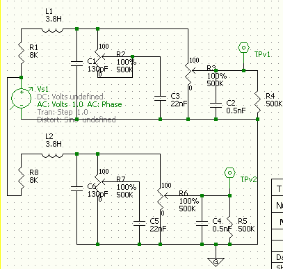 Here are the results, plots from both circuits overlaid, with the tone pots at 0, 25%, 50%, 75% and 100%  The curves for each tone pot arrangement are very close, in fact it is only the left curve , representing max treble cut) where they are visibly distinct, and only by about 1/3 db max. So I think that third pot grounded or not does not affect tone. There’s not many other issues to decide if one is better. Maybe if the pot became a bit scratchy, the grounded lug would slightly reduce noise, as it could not go fully open circuit? John EDIT While I’m about it, I thought Id use the same system to test the bass cut control. Now the values are changed to match ozs design, with a single coil pup modelled, and the bass cut either full on or fully off, resulting in two groups of curves as the treble cut is swept: 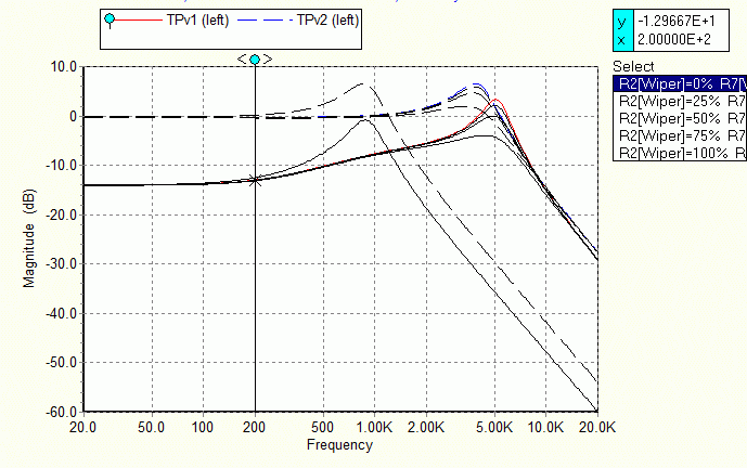 |
|
|
|
Post by ozboomer on Jul 4, 2010 8:29:54 GMT -5
"The best laid plans..." comes to mind tonight... Didn't get to wiring this weekend  ...but did manage to mount the "new" components onto an old pickguard, viz: The idea with this is to do the wiring "at my leisure"(!), checking as I go... and then, on TheBigDay(tm), I'll only have to remove the "loom" from this old pickguard, install all the electronics in the pickguard currently on the Bullet and solder-up the bridge ground and the output jack wires... and it means I can keep playing the Bullet while I'm wiring-up the new "loom"... Note: Other than the advantage of wiring "externally", the only reason I'm going through all this is that the Bullet has had a couple of goes of re-drilling the pickguard mounting holes and the thing is half-full of filler (not really) and I don't want to have to re-drill the body AGAIN... Anyway, too blinkin' busy... Maybe I'll get to starting next weekend  ... |
|
|
|
Post by sumgai on Jul 4, 2010 16:48:41 GMT -5
ash, First, thanks for finding that. You are now officially elected as our Archivist! ;D Yes, I said that, but remember, wherever you have a voltage, if you also have a resistance (or an impedance), you also have a current. The very low current coming out of the pup, coupled with our nominal-value pot, explains why we have such low capacitor values in the "bass" circuit, values that otherwise would be associated with low-band radio stuff. (160-80 meter ham bands, for starters.) In point of fact, you can bypass a cap with a variable resistor, and have a noticible effect, but as both fobits and ozboomer found out, there are some limits, and depending on other factors, component values don't often turn out as initally expected. Thus the need for constant experimentation. (As illustrated by our "normal" tone control - even though we know what's what, we still monkey around with it all the time, in hopes of somehow getting a better Tone.) Oh, and I don't recall ever claiming any kind of "ownership" for this circuit - I merely brought it to light, in response to a question. If I'm not mistaken, it was originally published in, again, the "Design Manual for Engineers", in the mid or late 1930's. But truthfully, I never bothered to research that fact to the bitter end. If I'm wrong, it won't matter - the basic concept and design is still older than dirt. ~!~!~!~!~!~ John, I'm not sure what I'm looking at here. If I've read the Legend correctly, it appears to me that the lower circuit has a resonant peak that's reduced in (dB) value, ostensibly thanks to the grounded third terminal on the tone pot. Sorry if I'm dense and was supposed to have an epiphany or sumpin'. Could you somehow persuade that chart to use different colors or linetypes or whatever, please? Thanks. sumgai |
|
|
|
Post by ozboomer on Jul 10, 2010 2:23:58 GMT -5
Here we go, folks... the next step in the saga I fully-wired the SimpleMod-b circuit today. The ol' screwdriver test on the pickups seems to work Ok and the components all seem to do what they're supposed to as well. To make things simpler to wire-up, I made a print of the wiring layout from earlier in this thread and as I completed a connection, I highlighted the wire. This made it simpler to see what had and hadn't been wired, viz: So, the final wiring (in the "temporary" pickguard) was completed in about 4-5 hours all-up; heh... I'm guessing an expert would probably do it something more than an hour(!). So, here it is: ...and a detailed view: Note that, for whatever reason, I just couldn't get the solder to stick on the back shell of the volume pot this time; whether my soldering iron is getting old and not so hot OR if the pot shell was dirty or something, I don't know. This is why everything is hanging off one of the lugs of the volume pot. Now, the next step is to take the pickguard out of the guitar, swap the wiring loom with what I've created today and then put the pickguard back in the guitar... and we'll see how things sound(!). More later... |
|
|
|
Post by ozboomer on Jul 11, 2010 7:02:57 GMT -5
*sigh* ... What a day. I won't go through the "blow-by-blow" (hmm... seems I've said that before, methinks)... Suffice to say, I had many adventures today... The primary problem was that, as I half-expected, the cutout in theguitar was not deep enough, so I couldn't install the pickguard with the push-pull switch+pot installed. I couldn't be bothered to wire-in a toggle DPDT for the blaster switch, so I simplified the whole thing right down and left only a "treble-cut" control in that position. Then I had problems with not being able to solder to a pot shell (I later worked out it must've been the material - the back of these pots look like a brass-y material, rather than the aluminium-like material on other pots I've used) and it was getting late in the day and blah blah blah... ANYway, I finally got the pickguard and wires, etc installed and I tried stringing-up a single string, plugged-in the guitar... and all the functions worked Ok.. thank goodness. So, I finished up with these functions in the guitar: - the "neck on" switch
- "treble cut" control
- "bass cut" control
- "treble bleed" function on the volume control
More photos and probably some sound comparisons to follow in the next few days... but I've had enough for today... I wonder if the "as built" version qualifies for the "General Guitar Schematics" sub-board?? John |
|
|
|
Post by newey on Jul 11, 2010 7:57:42 GMT -5
Sure, please post it there. But since this thread now runs to 8 pages and 105 posts, we'll need the condensed version! |
|
|
|
Post by ozboomer on Jul 15, 2010 19:16:57 GMT -5
Quick question, folks...
Just looking at another option (there's always another option!)... and wanted to know if there's any such thing as a 3PDT mini-toggle switch that runs as ON-ON-ON. Even ON-OFF-ON seem to be like hen's teeth here in Oz...?
Thanks...
|
|
|
|
Post by JohnH on Jul 16, 2010 16:07:13 GMT -5
I've not heard of a 3 pole on/on/on.
Jaycar will sell us dpdt on/on and on/off/on, plus three and four pole on/on switches.
To obtain a 4pdt on/on/on, south of the equator, would seem to require the services of a long-distance carrier pidgeon.
John
|
|
|
|
Post by sumgai on Jul 17, 2010 0:03:42 GMT -5
To obtain a 4pdt on/on/on, south of the equator, would seem to require the services of a long-distance carrier pidgeon. Chirp! Chirp! |
|
|
|
Post by ozboomer on Jul 17, 2010 6:03:52 GMT -5
So to some more detail about the "as-built" version of SimpleMod-b, including some photos and sound bites. The details of the "final"(!) design and the wiring layout can be found at SimpleMod - The Design. The overall layout on the back of the pickguard: ...and the detailed view: It all sounds Ok, I think... but it's still no MIA model. Some example sounds: - some basic sounds made with the previous wiring arrangement, SimpleMod-a (but built without the
inductor/extra tone control) - SimpleMod-a Sounds
- similar sounds made with SimpleMod-b; I think the "new" pickups sound a bit brighter/better than the ones installed before - SimpleMod-b Sounds
- a demonstration of playing using the middle pickup but with progressively increasing amounts of "bass cut" - SimpleMod-b Bass Cut
A slight problem I've found, though... I think I must have a few dry joints in the circuit OR there is an earthing problem somewhere OR the DPDT "Neck On" switch must have some problem as I hear crackles and pops when I touch nothing except the DPDT switch. Even stranger, when I plug the guitar into the computer I don't hear the noises very much (but they ARE there - but I only hear them when I have the monitoring volume set pretty high)... but when I plug the guitar into the amp (Frontman 15R), the crackles are significantly louder. I checked the circuit over with a meter before assembly and didn't find anything untoward... but I guess I must've missed something. Anyway, the following MP3 is what I hear when I touch the DPDT only... and then you'll (just!) hear when I touch the strings, and then raise my fingers... twice (you'll need to have your volume turned-UP a mite to hear the 2nd portion) -- SimpleMod-b NoiseOverall, though, I think the application/design has proven itself Ok... and the "bass cut" control certainly is a worthwhile addition to the standard "treble cut" control. John |
|
|
|
Post by ozboomer on Jul 17, 2010 6:08:01 GMT -5
To obtain a 4pdt on/on/on, south of the equator, would seem to require the services of a long-distance carrier pidgeon. Chirp! Chirp! The details of where this is coming from will become apparent soon... It's all about the modules I've written about elsewhere... and the 3PDT thing was to completely isolate a pickup when moving it between parallel / off / series connections... but more about this later... |
|
|
|
Post by ozboomer on Jul 17, 2010 7:42:07 GMT -5
Here's a couple of thoughts on the ideas I alluded to above, about adding a pickup in parallel, in series or not at all: The first version only needs a DPDT switch... but it takes advantage of the layout of the circuit, using common ground lines, and separate parallel outputs for the "original" and the additional "parallel" signal... and can therefore "get by" using only a DPDT. The second version is a draft design that isn't dependent on the layout of the circuit it's being loaded into; any input can have a pickup placed in parallel, in series or can be kept out of circuit... but it needs a 3PDT switch with the middle position "ON" (connected). It may be redundant/wasteful to have another pole... but it seems we might need to employ the "Grace L Ferguson Airline and Storm Door Company" "Sumgai Carrier Pigeon and Parts Delivery Service" to grab a 4PDT w/central ON to try in the circuit ;D At any rate, one of the things I remember from earlier discussions was that a pickup with its "hot" connected and its "return" left floating can act like an antenna for noise.. and I couldn't immediately think of a way to keep the additional pickup grounded and yet out of circuit ("n/c"), so I opted for the additional pole, to completely isolate the pickup when "n/c" is selected. As always, I'd appreciate any thoughts, etc... as I think a series connection of a pickup may be the next option ( SimpleMod-c here we come ) John |
|
|
|
Post by sumgai on Jul 17, 2010 16:56:22 GMT -5
John II,
A DPDT switch can do the job, and leave your drawing as a module than can be plugged in anywhere.
Four steps:
1) Eliminate S1c - the pup's hot lead is always connected to the output line;
2) Leave S1a alone - it's good the way it is;
3) Disconnect S1b's center terminal from ground, and instead connect that terminal to the pickup's hot lead - meaning, in the center position, both pup leads are always connected to the outgoing signal line, thus rendering the "hanging hot" issue null and void.
4) Profit!!!
HTH
sumgai
|
|
|
|
Post by ozboomer on Jul 18, 2010 6:00:10 GMT -5
A DPDT switch can do the job, and leave your drawing as a module than can be plugged in anywhere. Okie, I've done what you described, thus: ...but I still need to clear-up my confusion with something... I'm not sure about what the switch arrangement we have here physically looks like. Looking at the arrangement of "one pole", we have an associated 3 "on" positions (that are all connected somewhere distinct), so there must be 4 connectors for each "sub-switch". So, the physical device must have 8 termination points...? So, how does this DPDT on/on/on switch work!? ...let alone the fact that it's US$14 against a locally- sourced standard DPDT for A$3... (!) Hmm... Seeing these weirdo switches are hard to find and expensive, I might be crawling back to the drawing board to try and get something simpler going... I dunno.. The contemplation continues... |
|
|
|
Post by JohnH on Jul 18, 2010 7:24:13 GMT -5
oz - what you are drawing suggests not a two pole, but a three throw switch, dt3t. But Dpdt on/on/on. look like normal dpdt's, ie with 6 lugs
What happens is that up or down is the same as standard, but there is a middle position in which one pole is connected up and the other down. There is no separate middle output lug.
|
|
|
|
Post by ozboomer on Jul 18, 2010 8:04:08 GMT -5
oz - what you are drawing suggests not a two pole, but a three throw switch, dt3t. Ya, Okie... Thought sumfin' like that was goin' on.. (DP3T?) Ohhh, Ok... Now THAT's a funny one... and I'll have to nut that out some, as to what it really means; how it will work/get wired into a circuit. Fanx! a heap, John (yet again)... |
|
|
|
Post by newey on Jul 18, 2010 8:18:03 GMT -5
Exactly. I've seen slide switches configured that way, but toggles are rare. Mouser lists several, but all of them are not stocked items, IIRC.
|
|
|
|
Post by sumgai on Jul 18, 2010 12:06:49 GMT -5
ozzy, ...but I still need to clear-up my confusion with something... Hey, you dreamed it up, I just modified it, that's all. I ain't takin' no flak for this one! ;D Actually, what you've accidentally stumbled upon is the very reason nearly everyone, JohnH included, draws a layout diagram instead of a schematic when using this kind of switch - it's hard to correctly diagram the switch operation in a schematic. But you did the right thing, and "ghosted" the middle position. You simply didn't "connect all the dots", that's all. We'll address that omission now. John #1 is more correct in his description. I used to rant and rail about calling a DP3T switch a DPDT on-on-on, but I guess I must've gotten tired of fighting City Hall or sumpin'....... I've given up, they can mis-label it all they want, I'll just continue to march, TYVM. To elaborate on John's monograph, look at your "upper" diagram, wherein you label the 6 terminals a thru f. In a nominally "normal" DP3T on-on-on configuration, you'd find these pairs connected: up - ac & bd mid - ce & bd dn - cd & df Now, armed with that info, let's go back and look at your "upper" diagram. (Your lower one has the "look and feel" of a standard Strat-style 'blade' or 'lever' switch, but is adaptable to what we're gonna do, if you label the terminals accordingly.) Both halves of your S2a need to have their labels flipped around - just swap the 'b' and 'f' labels on your drawing, and the 'a' and 'e' labels, leave all the wires alone. You'll see why in a moment. Now for one mod..... For S2b, take that 'n/c' (mid) and connect it to 'e'. Thus modified, your new "logic" becomes: up = The bd pair connects pickups 1 & 3 to ground, so they're good, and, the ac pair connects pickup 2 to the output line, so we have a parallel combo. mid = The bd pair still connects pickups 1 & 3 to ground, so they're still good, but now the ce pair is connected, and it's going nowhere, so pickup 2 is off (and not hanging hot, either). down = The df pair goes to the ce pair, so instead of pickups 1 & 3 going to ground, they go to the hot side of pickup 2, which yields a series combo. Sorry I don't have a drawing for you at the moment, I'm in a bit of a rush.....  But to quickly recap, each of the switch terminals will be connected like so: a - output line b - ground c - pickup #2's hot lead d - pickups 1 & 3 ground leads e & f are shorted together Gotta go..... HTH! sumgai |
|
|
|
Post by ozboomer on Jul 18, 2010 21:00:49 GMT -5
...but I still need to clear-up my confusion with something... Hey, you dreamed it up, I just modified it, that's all. I ain't takin' no flak for this one! Ya, ya... I know.. "Why must you (I) make everything so complicated!?" is the story of my life...(!) ;D Ok... So, for example, it might be more helpful to show the connections between the "centre" position and one of the (complimentary) "outer" positions as being "internal" connections, something I don't have to wire but is defined by the switch construction? (see the diagram below to better illustrate what I'm trying to say by using too many words).. Well, now you've explained the workings, I can better understand that when we use this sort of switch, it should be obligatory that we illustrate/explain how the connections are made AND say something like "it's just the way this thing works". Otherwise, one could be making "Johnisms" (or should that be Ozisms) and write-up things without (totally) knowing what one is talking about(!) Anyhoo, the modified "standard" diagram, from what I understand of your description, is: Now, if you'd confirm that I haven't got my wires crossed (again), I'll make a similar update to the "add it anywhere" version. Fanx! for shedding lots of light on the subject... again. John |
|
|
|
Post by ozboomer on Jul 18, 2010 21:08:27 GMT -5
Exactly. I've seen slide switches configured that way, but toggles are rare. Mouser lists several, but all of them are not stocked items, IIRC. Uh-huh... and is why I'm still letting things gel in my head some, 'coz it looks like these DPDT/on-on-on things are going to be kind of hard to get a'hold of, as well as needing $$$ - I'll have to get some better understanding before I start a'building, methinks... BTW, anyone have any confirming/debunking thoughts on the "crackles" I'm sometimes hearing in the build I've described above? Fanx! again, folks... |
|


 - so in this design, I've also included:


 So, Fanx! for highlighting the trouble...!


 ...but did manage to mount the "new" components onto an old pickguard, viz:
 ...
... 


 But to quickly recap, each of the switch terminals will be connected like so: