|
|
Post by flateric on Feb 24, 2010 17:20:12 GMT -5
|
|
|
|
Post by ijustwannastrat on Feb 24, 2010 20:50:44 GMT -5
Seriously, you should consider making these to sell. Not as a way to make a living, just for fun on the side. I know if you started a store on ebay, I would probably be your best customer.
|
|
|
|
Post by ashcatlt on Feb 25, 2010 3:07:20 GMT -5
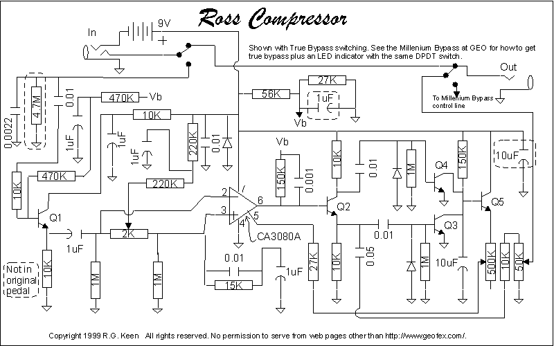
Anybody wanna explain how this thing does what it does? It's based on the Ross Compressor, which people talk about all over the place, but I can't find a good "technology of..." type article anywhere. I tried to follow the schematic, even looked up the datasheet for the chip, but I'm afraid it's just a little bit outside my league.
Edit - spose I should say that your stuff always impresses me. I'm embarrassed to think how many pedals you've built in the years I've been sitting staring at the parts for my Rat.
|
|
|
|
Post by flateric on Feb 25, 2010 4:30:24 GMT -5
Heh, its all paint by numbers for me, i just follow the instructions, don't know how they actually work!
|
|
|
|
Post by D2o on Feb 25, 2010 11:56:37 GMT -5
Heh, its all paint by numbers for me, i just follow the instructions, don't know how they actually work! You are modest, sir. I have tried to build little things like this and boogered up the tiny solder joints and caused male pattern baldness. You are a good circuit builder. D2o |
|
|
|
Post by ashcatlt on Feb 25, 2010 13:46:41 GMT -5
Well, here's the schematic:  Not sure how yours differs, but from what I can tell it's pretty close. It looks to me like it uses a rectified version of the signal to adjust the voltage on pin 5 (bias input) of the chip. Not sure how that affects compression, though. My understanding of these things would say that adjusting the bias away from half the supply voltage would cause it to run out of headroom on one side of the waveform only, which should lead to a sort of asymmetrical clipping. Pretty sure I'm missing something important here. |
|
|
|
Post by flateric on Feb 25, 2010 18:18:56 GMT -5
While I wait for my CA3080 chip to arrive from ebay, I've finally got a satisfactory technique for the enclosure graphics. I do the design in photoshop, print off a paper copy to use as template for the switches, pots, leds, etc. then reverse the image and print it onto ink-jet transparency paper. Let it dry for an hour.
Rub down the enclosure with fine emery to get a nice shine then using a very thin and even smear of araldite epoxy, stick the printed transparency down to the enclosure printed side down.
You get a nice crisp image, plenty of colour, no messing with dry rub or decals, and its self-protected by the acetate sheet its printed onto. Looks almost professional:)
|
|
|
|
Post by ijustwannastrat on Feb 25, 2010 21:46:31 GMT -5
What do you mean, "almost". Your stompboxes are looking very spiffy.
I am SO tempted to try this. I've never worked with circuit boards though, so I'm a little weary. If I knew how they worked, I would do it in a heartbeat. Maybe that's this weekends project.
|
|
|
|
Post by flateric on Feb 26, 2010 4:45:02 GMT -5
|
|
|
|
Post by sumgai on Mar 1, 2010 1:15:16 GMT -5
It looks to me like it uses a rectified version of the signal to adjust the voltage on pin 5 (bias input) of the chip. Not sure how that affects compression, though. My understanding of these things would say that adjusting the bias away from half the supply voltage would cause it to run out of headroom on one side of the waveform only, which should lead to a sort of asymmetrical clipping.
Pretty sure I'm missing something important here. Want a detailed analysis? There ain't enough time.  But in short, here's what happens to cause compression. A look at the datasheet ( CA3080) tells us that the Adjust pin controls the bias point for the pair of transistors that first see the incoming signal. By controlling the voltage here, we control the gain. The big difference between this and using the normal method of controlling an op-amp's gain (dividing the feedback resistor by the input resistor (R F/R I)) is that when you solder in those resistors, the gain factor is fixed. With the Adjust pin, the gain can be adjusted on the fly - perfect for a compressor! Enter that bunch of transistors and stuff tied to the CA3080's output. Long story short, Q5 keeps the Adjust pin tied pretty high, nearly as high as the battery itself. That sets the gain at nearly full out. When the signal from the IC's output goes through Q2 and Q3/Q4, it modulates the voltage applied to Q5, thus turning up and down what comes out of Q5, and thus what control voltage will be applied to the IC. (The diodes don't rectify, they set a minimum level so that the transistors don't go so low as to completely shut off the IC.) The beauty here is, it's done in sync with the actual signal itself, no delays at all.  (IOW, there should be no "breathing" effect, the sound doesn't hesitate between louder and softer.) What it boils down to is that as the signal gets louder, the gain factor is reduced, and of course the opposite is true. So what you hear is a steady-level signal.... or at least, that's what you should hear.  HTH sumgai p.s. A lot of Electronical Theory was harmed in the making of this message. My apologies and condolences to the next of kin. |
|