spudler
Rookie Solder Flinger

Posts: 24
Likes: 0
|
Post by spudler on Mar 28, 2010 17:39:52 GMT -5
I hope it is ok to post this here? It is not technically a AMP question but without the speaker cab the amp would be useless. lol
I was givin a set of PA speakers. I call them that because there 3X the size of the home speakers I had. I hve a 15" driver and I believe a 2" horn. I found a X-over behind the input cover. I can see it says Soundtech CX4 on the plate. The sticker that is supposed to be attached to the panel listing Model#,Serial#,Power rating/RMS and Freq Response looks like it was never attached. I tried a search and all I found so far are monitor speakers and the have the exact same input plate. Mine are not monitors as they are 36"H X24"W X15" D. Approx.
I am trying to figure out the X-over so I know what frequencys it is filtering and so on. I did notice on the 15" driver lead there is only a Inductor I believe it looks like a spool of wire, in between the input plug and the lead to the + side of 15" driver (what is that for??) now on the horn its a little tricky first the wires are out of phase and then there are 2 fuses, a CAP reading 2.2uf then there is a another cap but inbetween the 2 caps there is another Transducer (coil of wire) leading to the ground of the input plug. there is another cap and it reads 6.8 uf and it connects to the - of the horn. I have found some info but nothing telling me what the transducers are for or what frequencys are able to get to the 15" driver and the horn and what is blocked, Is anything blocked from the 15" driver? The transducers read 0 resistance also.
Thanks If you have links that would help me please let me know I love pages with info I can read about amps, cabs, speakers etc. anything audio is fantastic.
|
|
|
|
Post by ashcatlt on Mar 28, 2010 21:29:55 GMT -5
Inductor is the correct word for the coils of wire. A transducer converts electrical to mechanical or vice versa - like a speaker or microphone.
An inductor in series will act as a low-pass filter. You might say it provides more resistance to higher frequency signals. The DC current that your meter uses to test resistance about as low a frequncy (0Hz) as you can get, and therefore has the easiest time getting through the inductor. There must be some resistance just from the wire, but apparently not enough to register on whatever setting you had it set to.
An inductor in parallel with the signal will provide a short circuit path for the lowest frequncies, which find it easier to complete the circuit this way than through the resistance of the speaker's voice coil. That is, it's a high-pass filter.
Caps work the other way. In series, they pass higher freqs more easily (and completely block DC) while in paralel, they shunt high freqs, acting as a low-pass.
How to calculate the cutoff? Well, somebody around here might be able to do it in their heads. I'd use pSpice or something similar to model it. Either way, though, we're going to need an idea of the inductance (in Henries) of the coils. I'm not sure that there's any good way to find this using a meter, though.
|
|
spudler
Rookie Solder Flinger

Posts: 24
Likes: 0
|
Post by spudler on Mar 28, 2010 22:34:56 GMT -5
wow thanks a ton. you don't mind if copy the message so I can refer back to it later do you?? I have never had the chance to work with passive second order crosovers before. I always ran my crossovers pre amps and had 1 amp for the lows 20 HZ to about 150 HZ at max and 1 amp for about 120hz to 18-20khz. I had 2 subs and 2 full range pa speakers I wish I could of went with a 3 or 4 way setup. I had a crossover to do that but I never could use it. I did one time run 3 amps but that was auto sound and I had 3 1000 watt amps set for 20-120hz 120hz to I think it was 3 khz the form 2 to 20 khz If I remember right It was 5 years ago and I started with 1 350 watt amp and just keep adding and changing things. I used to have people poke fun at me cause I was always changing speakers or amps or wiring in power caps etc. It sounded really nice though.
I have a cheap Multi meter it is digital but its no fluke or anything. It has done fine for me so far. but I can see I should invest in a good meter if I am going to be doing amp, guitar , crossover work.
I will look and see if I can find a way to figure that info out. My meter only goes to 200 ohms and up to 2000k ohm.
|
|
|
|
Post by ashcatlt on Mar 28, 2010 23:23:28 GMT -5
You asked for links. This one explains at the end why the HF driver is wired "out of phase" as you say. A 2nd order filter creates a 180° phase lag. Wanna watch a big dork wire a crossover from scratch?: Can you hook us up some pics of your unit?...ahem...I mean your crossover, this is a family friendly forum!  |
|
spudler
Rookie Solder Flinger

Posts: 24
Likes: 0
|
Post by spudler on Apr 12, 2010 8:44:52 GMT -5
ya no prob. Sorry for delay I am time strapped trying to fight college charges that are because of their unreliable servers,doing a guitar build,trying to practice songs and play my guitar daily,fixing a dead Sunn SR8520P mixer amp. I swear the day has gotten way shorter.
|
|
spudler
Rookie Solder Flinger

Posts: 24
Likes: 0
|
Post by spudler on Apr 12, 2010 13:08:16 GMT -5
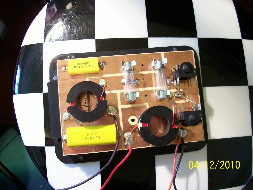 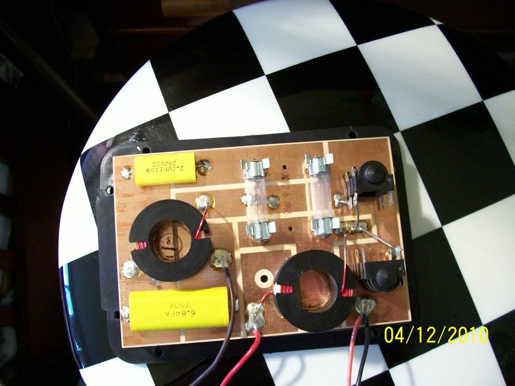 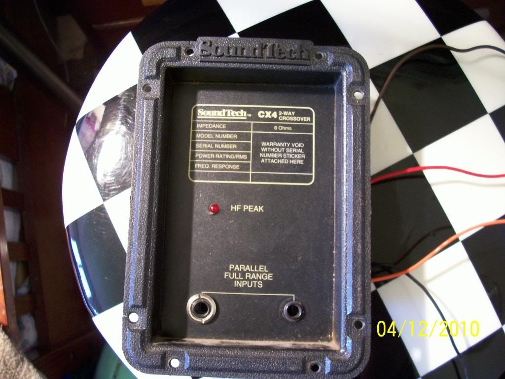 Here are some pics. the side with the caps is the horn side. The one with just the Coil is the driver or sub side. |
|
|
|
Post by sumgai on Apr 12, 2010 16:51:04 GMT -5
spudler, I will look and see if I can find a way to figure that info out. Beyond your meter, all it's gonna take is an inexpensive frequency generator. Got one of those laying around?  sumgai |
|
spudler
Rookie Solder Flinger

Posts: 24
Likes: 0
|
Post by spudler on Apr 16, 2010 19:16:34 GMT -5
I don't think so. I have never really had to test or repair equipment before. I am also used to pre amp crossovers. I used a (Can;t remember the name now) 2-3-4 way crossover in the club I only used 2 since I had 1 amp for subs and 1 amp for the mains worled perfectly. Other than that I had a awesome auto system but same thing I had 3 seperate outputs from head unit with a adjustable crossover for each and my amps had crossovers I could dial in. I like this stuff it is very interesting and I have noticed lately most audio systems for sale are dialed in more for 5.1 etc and not for true quality sound with those 3" speakers and a 8 sub
|
|
|
|
Post by ashcatlt on Apr 17, 2010 12:53:18 GMT -5
I think that what you've got here is a first order low pass filter for the LF driver, and a third order high pass for the horn. If we knew the impedance of the horn driver, I'm pretty sure we could figure out the cutoff of the high pass from the cap values. From there we could deduce the inductance of that coil. We might then make an assumption re: the cutoff of the low pass, and (given the Z of the LF driver) come up with an estimate for that inductor. Then again...butt..u...me...  I think that sumgai was implying that we could use a frquency generator to figure the inductance of the coils. We could also use this to find the impedance of the drivers. With those values it would be elementary to figure the cutoff freqs. To me, though, it seems it would be much easier to just run that generator through an amp into the cabinet. Run a sine sweep and record the output of one speaker. We would repeat with the other speaker and then analyze the response. This is subject to some complications, but I think it would do well to find a ballpark figure for the crossover point. There are a number of freeware sine wave generators out there. |
|
|
|
Post by sumgai on Apr 17, 2010 23:16:56 GMT -5
spudler, First, kudos to ash for reminding us all that software has taken over the test world! My old but still servicable gear just doesn't give me any reason to remember that little bit of advice.  I've come to realize that it'll take only a meter and a generator, physically speaking, but it'll also take about 50 to 100 measurements, and no less than 18 or 19 steps of some fairly hairy math, for each measurement. It can be done, but at this point, that's too much effort.  Instead, it would be easier, and just about as accurate, if you simply do your best to determine the number of turns, the diameter, and the length of each coil, and then plug those figures into a calculator found any one of hundreds of websites. Google for "calculate coil inductance", or something similar. HTH sumgai |
|
spudler
Rookie Solder Flinger

Posts: 24
Likes: 0
|
Post by spudler on Apr 26, 2010 0:20:49 GMT -5
ok so I take and rune this sweep through my amp and speakers and listen to what frequencys are high and drop off on each of the soeakers?? Ie the 15" driver and the 1" horn unit? BTW both speakers are 8 0hm. I did get info on both the 15" drivers are not original I used the original ones in my club setup as they sounded better. the 15" I have are Cetec Gauss 4583A and the Horns are Foster H025n08. I was lucky enough to get the specs on the 15" so I know what frequency they work best at and what crossover they recommend using. the say a 800HZ as I have found that they don't actuallt stop any frequency above thet they just roll off the power for anything above that.That is the highest X-over recommended. as the speaker response is from 35hz to 2500hz. although I have found a rebuild kit with newer and higher quality material and I can get the frequency down to 21hz with the better material alows the speaker to move much easier.
I had not known of the sine wave generators before but I do have a cd of bass stuff for adjusting and tuning auto sound systems. I have one that runs from 10hz to 20,000hz and it loops that up and down a few times I believe it is about a 3 min wav file. I did know when I did my Jeep the higher frequency drove me out of the vehicle even at low volume as I felt my head would explode lol. the lower frequencys caused my eyes to water and my rearview mirror to fall off lol.
|
|
spudler
Rookie Solder Flinger

Posts: 24
Likes: 0
|
Post by spudler on Apr 26, 2010 0:34:09 GMT -5
If there is a way to attach the .pdf of the LF driver specs I will do that. since it is not a .jpg I cant add it to my photobucket and ste as a image. I could probably print it and scan it as a .jpg but if I can do it easier I would like that. The spec sheet has alot of info I have no idea what it is. Oh I can do a snip I forgot about that cool feature and save as a jpg. I will do that right now. 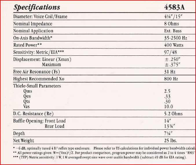 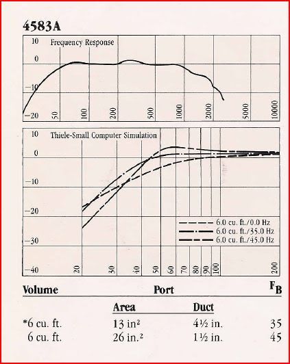 All the Free Sine Wave Generators I have found use the sound card I don't want any limits of the soundcard to influence the sound generated. I hope to find one I can use to make a wav file then transfer it to a device that can reproduce the whole spectrum and not limit what I can send to the speakers. I know the amp I will be recieving and using can go from 1hz to above 20,000hz but they recommend 20 hz to 20,000hz. |
|
|
|
Post by ashcatlt on Apr 27, 2010 2:11:37 GMT -5
How precise are you looking to get here?
I certainly wouldn't recommend running the test by jamming your ear into each driver and cranking it up! I'd put a relatively flat mic up next to each driver and record the results. Then use software to analyze the results.
My (educated, and sort of corroborated by your post above) guess is that the crossover point will be somewhere within the relatively flat region of your soundcard's freq response. Likewise most any mic you might put in front of it.
|
|
spudler
Rookie Solder Flinger

Posts: 24
Likes: 0
|
Post by spudler on May 4, 2010 21:37:58 GMT -5
oh darn no mic here at the moment. I am actually using a Digitech GNX4 workstation as the sound card when I am running guitar etc. I use my sony home theatre the rest of the time. I think it is about 1khz to 1.2khz. I did find that the LF drivers don't do much below 35-40hz. I am actually going to use a peavey PL800 crossover and BI-AMP the CS800 so I will be good once the crossover shows up. I can also dial back the highs and try to match power a little better. as it sits the highs are way loud compared to the lower frequencys. I read thats typical.
I am sure happy with the sound compared to what I was using though. I forgot what real sound out of real speakers sounded like. my eyes even started to water a bit.
I am shocked thought I shouldn't be at how much quality is lost on the 5.1 systems with those teeny satelite speakers.
|
|