TheLivingDead
Rookie Solder Flinger
 We live thinking we'll never die. We die thinking we never lived. Cut it out.
Posts: 8
Likes: 0
|
Post by TheLivingDead on Sept 12, 2010 22:56:59 GMT -5
Alright, I've got this going on but I want position 4 to have both pups selected and out-of-phase.  Is that possible? If so, how do I make it happen? I have two DiMarzios by the way. Thanks for any help. |
|
|
|
Post by newey on Sept 13, 2010 5:56:42 GMT -5
Living Dead:
Hello and Welcome!
What you want is certainly possible with a Superswitch. Unfortunately, there's going to be quite a bit of re-drawing of that SD diagram involved, and I can't do it right this minute (work calls . . .).
Now, have you actually wired this up and have it working as shown in the SD diagram?
While a diagram would be better, perhaps if I explain what I would do, you can redraw it and we'll check it for accuracy:
1) We'll leave the bridge pickup "as is", and reversed the phase of the neck pickup. Remove the red and white wires from the neck pickup from lug #4 on the upper right pole of the switch. Connect the two together and tape off the connection.
2) Remove the neck pickup green wire from the back of the pot. Leave the shield soldered to the pot.
3) Remove the neck pickup black wire from lug #3 on the upper left pole. Also remove both the jumper wires to #4 and #5 of that pole.
4) Solder the green wire to lug #4 of the upper left pole (where the black was connected before.)
5) Solder the black wire to lug #4 of the upper right pole (where the red and white wires were previously connected)
6) Connect 2 jumper wires from the black wire at lug #4 on the upper right to lugs # 3 and #5 on the upper left pole, respectively. (These are the ones that were previously all jumpered together with the black wire).
7) Connect 2 jumpers from the green wire at lug #4 of the upper left pole to lugs #3 and #5 on the lower right pole, respectively.
8) EDIT: Almost forgot, we still need to get the bridge pup on at position 4. To do so, simply add a jumper from the black bridge wire on the lower left pole over to lug #4 on that pole.
That should do it, but I understand if verbal directions aren't clear- if so, you'll need to await a diagram. And, there may well be an easier way- if there is, someone will chime in.
|
|
TheLivingDead
Rookie Solder Flinger
We live thinking we'll never die. We die thinking we never lived. Cut it out.
Posts: 8
Likes: 0
|
Post by TheLivingDead on Sept 13, 2010 14:28:57 GMT -5
Ok! I'm pretty sure I did as you instructed:  I also got this from another guy over on jemsite: 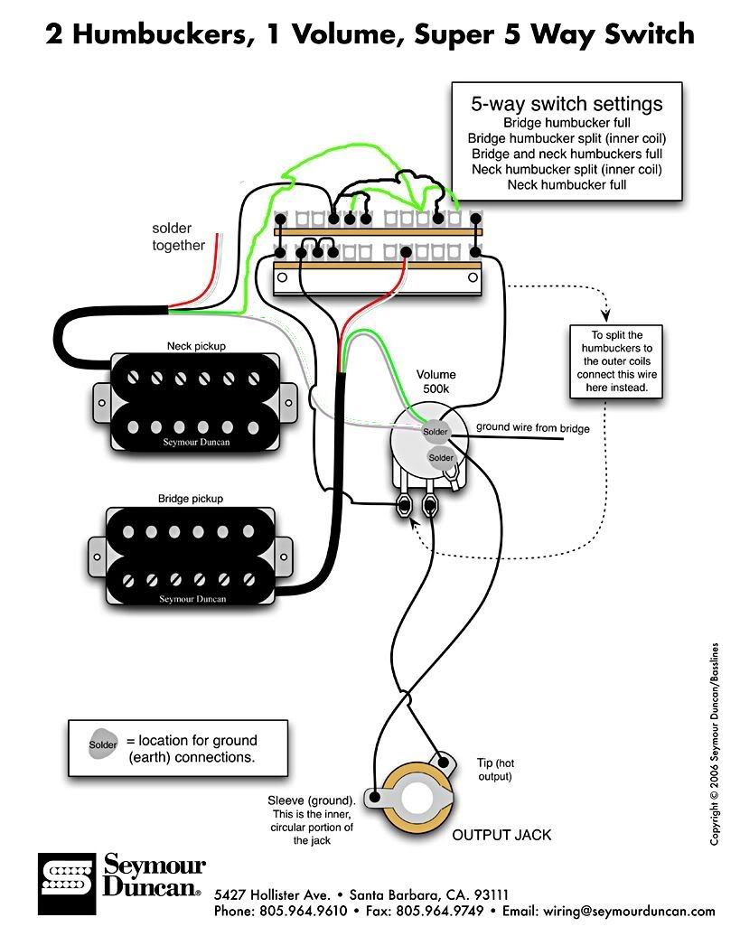 Of what I understand, I think yours is what I'm looking for.  Oh and to answer your question, no I don't have this wired up already. But I have no problem tackling this kind of thing. Thank you so much for your help!  |
|
|
|
Post by Yew on Sept 13, 2010 14:40:08 GMT -5
Protip. its easier to solder to the side of a pot, than the big glob of solder that factories use for primary installs.
|
|
TheLivingDead
Rookie Solder Flinger
We live thinking we'll never die. We die thinking we never lived. Cut it out.
Posts: 8
Likes: 0
|
Post by TheLivingDead on Sept 13, 2010 14:46:11 GMT -5
Protip. its easier to solder to the side of a pot, than the big glob of solder that factories use for primary installs. Yeah? I just rough up the surface with sandpaper and it's pretty easy for me. I might try that though. |
|
|
|
Post by newey on Sept 13, 2010 15:30:21 GMT -5
LD- Both diagrams are equivalent- I just used the lower right-hand pole for the ground connections since it was mostly empty. But either one should work. Although (as we always add around here) best to allow someone else to independently verify any diagram before you fire up the iron. I've been wrong before, and fairly regularly!  . EDIT:Just realized, your Jemsite guy did what I forgot to do at first, add the bridge pup in at position 4! (See my edit at Step 8 above.) That jumper needs to be added to his diagram. |
|
TheLivingDead
Rookie Solder Flinger
We live thinking we'll never die. We die thinking we never lived. Cut it out.
Posts: 8
Likes: 0
|
Post by TheLivingDead on Sept 13, 2010 15:56:35 GMT -5
Hah! Alrighty, so it looks like this will do the trick, if two different people came to the same conclusion. I'll ask around to see if anybody can verify it, but even with my basic understanding I think it'll work. I've got to order the superswitch right now and when it arrives I'll get this all wired up. I'll let you know how it goes! Thanks again, newey! |
|
|
|
Post by sumgai on Sept 13, 2010 16:53:47 GMT -5
I'll sign off on it. Looks good from here.
sumgai
|
|
TheLivingDead
Rookie Solder Flinger
We live thinking we'll never die. We die thinking we never lived. Cut it out.
Posts: 8
Likes: 0
|
Post by TheLivingDead on Sept 13, 2010 17:42:05 GMT -5
Fantastic! |
|
|
|
Post by newey on Sept 13, 2010 22:35:59 GMT -5
At the risk of being obvious, I'll just add that all of the above is based on SD wire colors, you'll need to map the diagram for you DMs' colors.
|
|
TheLivingDead
Rookie Solder Flinger
We live thinking we'll never die. We die thinking we never lived. Cut it out.
Posts: 8
Likes: 0
|
Post by TheLivingDead on Sept 13, 2010 22:54:34 GMT -5
Yup, I know. ;D
|
|
TheLivingDead
Rookie Solder Flinger
We live thinking we'll never die. We die thinking we never lived. Cut it out.
Posts: 8
Likes: 0
|
Post by TheLivingDead on Sept 22, 2010 20:56:40 GMT -5
Worked like a charm! Thanks so much guys! |
|
|
|
Post by sumgai on Sept 23, 2010 21:50:58 GMT -5
Worked like a charm! Thanks so much guys! Ah, ah, ahhhh, not so fast there, buddy-boy! Before you can say "done", you have to post pictures and sound clips in The Gallery. Then the project is finished! ;D sumgai |
|
TheLivingDead
Rookie Solder Flinger
We live thinking we'll never die. We die thinking we never lived. Cut it out.
Posts: 8
Likes: 0
|
Post by TheLivingDead on Sept 23, 2010 23:07:14 GMT -5
Hah! Alright. I can supply the pics but I have no way of getting any audio atm. Sounds great though! Especially position 4, the out-of-phase position. Almost wah-like and the harmonics just jump out! I'll get some audio clips up when my new amp arrives and my new recording setup is finished next week. After I got the jumpers taken care of:  Looks kind of sloppy, I know, but I assure you everything works properly.  And just for good measure, here she is with the new switch:  Yeah! I love it. Now I'm looking at all my other H-H guitars...  Thanks again for all the help, everyone. Couldn't have done it without you. |
|


 .
.
