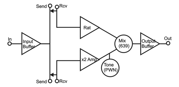
Okay, I ain’t makin’ no schematic for this puppy! Honestly there isn’t much original in any of the individual modules involved. I figure a flow chart, a couple links, and some text should get the point across.

It’s built around an LM324 quad op amp
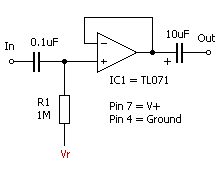
The input buffer is pretty much this:

Except I think the output cap is 4.7uF cause I had a bunch of those, and it’s at least big enough.
The insert jacks are switched stereo jacks (ripped out of a patchbay). Tip is Send and Ring is Return. With no plug inserted these are shorted together.
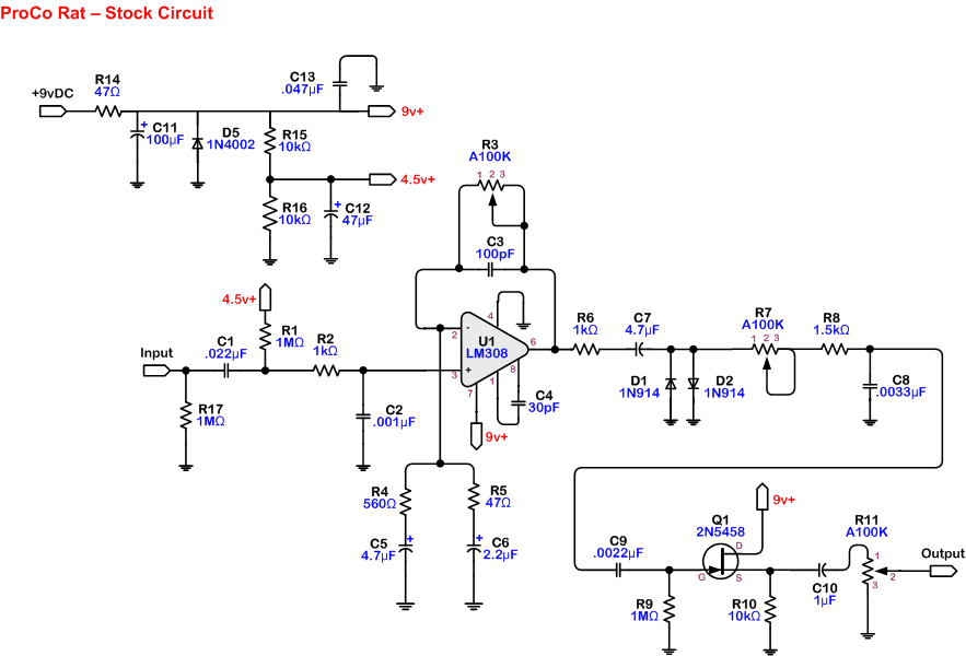
The “Rat” section is about exactly this:

Obviously, the opamp is actually one section of the LM324. I think the input cap is bigger than C1. The gain pot (R3) is replaced with a 140K fixed resistor. The output cap (C7) is cut down to 10nF, which seems to put the cutoff somewhere just over 300 Hz. I think I left R7 out all together, but I may have put some small fixed resistance there just to knock down the highest harmonics coming out of the diodes. Mine leaves off all the components after C8, and heads straight off to the Mix pot. We’ll get back to that.
The “x2 Amp” is essentially that same buffer from above, but with a 1:1 voltage divider in the feedback loop. Interestingly, I found that with the “bottom” resistor connected to 0V I got nothing through this stage. Connecting it to 4.5V got me the 2 x gain I was looking for.
After that clean amp stage comes the Tone (PWN) control. It’s wired just like a guitar’s tone control: 100K variable resistor > 10nF cap > ground. I tried it with the variable resistor in series with the output (like R7 in the Rat), but I wasn’t happy with it. It was almost too much, and it seemed to affect the distorted sound more than I wanted.
Now we’re back to the Mix (639) pot. This is a 500K log pot. 100K didn’t allow enough separation on either end and also seemed to help the PWN knob affect the distorted signal.
First thing I found was that the distorted side was a bit too much louder than the clean side. So I dropped a 1K or 1.5K resistor to ground at output of the distortion, basically parallel to C8. This about halves the output and makes it just enough louder on that end of the pot.
Then I found that there wasn’t a very good balance in the middle of the pot’s travel and it just suddenly went all distorted pretty quick at the end. Reversing the pot didn’t work, or reversed the problem. I stuck a 187K (convenient) resistor between the distortion’s lug and the wiper and it works just about perfectly. It doesn’t get quite completely clean, but that’s what the switch is for.
The wiper goes to the output buffer which is exactly the same thing again. Output from here goes to the switch.
Just realized that the bypass switch isn’t pictured in the flow chart. It’s a buffered bypass. The output from the Input Buffer actually splits 3 ways – to the Tips of the insert jacks and to the bypass side of the switch. The output from the Output Buffer goes to the other outside lug on the switch, with the actual Output Jack on the common. That’s only one pole on a DPDT. The other pole will make the LED work, but I need to decide if I’m refinishing the thing before I glue the LED in.
The power supply for the whole thing is exactly that from the Rat, though it's also drilled for and will soon include one 2.1mm DC input and 4 x 1/8 inch DC output jacks with filtering caps exactly like I built into my
Tuna Can. It will power the pedals in the insert loops!
All four opamp sections use 1M bias resistors to the Vref. The 3 later stages likely could have done with much lower resistors and possibly had better noise specs. From what I've heard, though, you can run into trouble if splitting a signal out to two loads which are very much different in input-Z. I figured that it was more likely than not that whatever might be plugged into one of the sends would be 1M (most of the pedals I own are around there) and I wanted it to not be too far off if there was nothing plugged into the
other insert. Then, I just had the 1M resistors in my hand so I stuck one in for the output buffer.
Anyway, it sounds really cool. With 639 set around 3 and the PWN knob up (or down…un-PWNed!) there is a really nice mix with quite a lot of distortion, but still a good deal of clarity and articulation. When it’s PWNed, you get a lot of nasty higher order harmonics with a nice thump down amongst the fundamentals. I’m gonna make Luke record the demo, so it might take a couple minutes, but I will get samples for y’all