jerry8jb
Apprentice Shielder

Posts: 30
Likes: 0
|
Post by jerry8jb on Jan 29, 2011 14:35:35 GMT -5
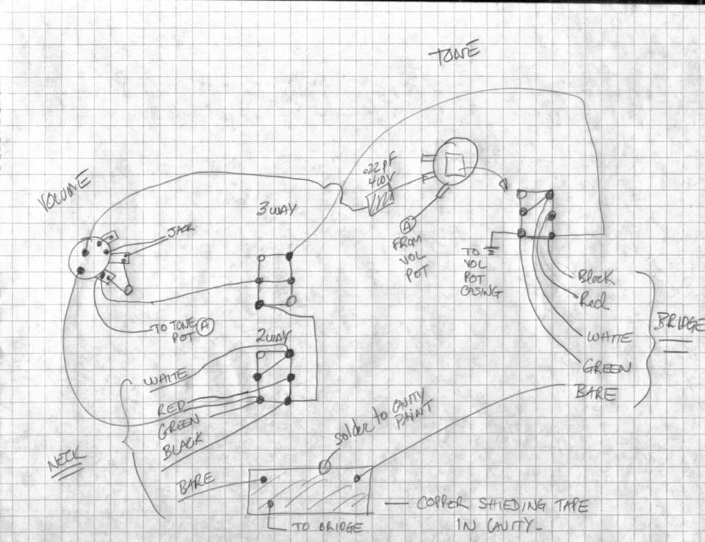
Hi guys, electronic is not mu cup of tea, so I need your help. I try to figure what the 2 way and the tone switch are doing. I was expected a coil slip or paralel/series but they seems to have no effect when I test. Another weird thing is the copper shield tape in the cavity bottom, looks like a partial shielding mod since not all grounds go there. Can someboby shed some light for me? Here is my drawing. Hope it works I'm new at posting image... Thanks. jerry  fixed by sumgai |
|
|
|
Post by newey on Jan 29, 2011 14:57:55 GMT -5
Jerry-
Your image didn't appear, so not much we can tell you. If you are having difficulty posting images, there is a tutorial in the Reference section.
|
|
jerry8jb
Apprentice Shielder
Posts: 30
Likes: 0
|
Post by jerry8jb on Jan 29, 2011 14:58:42 GMT -5
fixed by sumgai |
|
|
|
Post by JohnH on Jan 29, 2011 14:59:19 GMT -5
I had a go at correcting the image link, but can't seem to make it work. Plaese check your image!
cheers
John
|
|
|
|
Post by JohnH on Jan 29, 2011 15:00:51 GMT -5
Ok, your second link can be made to work: |
|
|
|
Post by newey on Jan 29, 2011 18:37:39 GMT -5
jerry- First of all, it is not necessary that all grounds go to a single point, although it may be desirable to do so. However, for shielding to have any effect, it must at some point be connected to the output jack negative; it is not clear that this is the case based upon the diagram you posted. Without knowing what the pickups and wire colors being used are, it is impossible to tell whether the 2-way switches do what they are supposed to do. The bridge switch looks like it is meant as a coil split, but again it depends on the wire colors and what coils they connect to. I can't tell what the neck switch is supposed to do, as it doesn't seem that the neck pickup is grounded anywhere, as none of the switch connections lead to ground. What is this diagram? Is it a drawing of what you have inside the guitar, or a drawing of how you wired it, or intended to wire it? Also, it would help if you turned it so we don't have to look at it sideways!  |
|
jerry8jb
Apprentice Shielder
Posts: 30
Likes: 0
|
Post by jerry8jb on Jan 29, 2011 22:19:25 GMT -5
Hi, This is what is inside the guitar as I received it. This is a Kramer Nightswan Aztec. This is a 2 humbuckers guitar, Seymour Duncan CCJ on the neck and a trembucker et the bridge. Here is the drawing rotated. I think that the switches are grounded thru a conductive paint. The SD color codes are GREEN = start of adjustable/south coil RED = finish of adjustable/south coil BLACK = start of stud/north coil WHITE = finish of stud/north coil The 3way switch works as a normal 3way switch = N-NB-B all both coils on. The 2way and the tone switch makes no differences all coils remains on, no split... Sorry for the sided pics, I'm at my first time posting images. Thanks. Jerry [img src=" ![]() i1104.photobucket.com/albums/h329/jerry8jb/KramerNightswanAztec.jpg i1104.photobucket.com/albums/h329/jerry8jb/KramerNightswanAztec.jpg"][/img] |
|
jerry8jb
Apprentice Shielder
Posts: 30
Likes: 0
|
Post by jerry8jb on Jan 29, 2011 22:22:56 GMT -5
Sorry I'm having problem with the dawn pic!!! |
|
jerry8jb
Apprentice Shielder
Posts: 30
Likes: 0
|
Post by jerry8jb on Jan 29, 2011 22:29:49 GMT -5
|
|
|
|
Post by newey on Jan 30, 2011 0:04:56 GMT -5
OK, I misspoke earlier when I said that the one two way switch looked to be a coil split. Using SD colors, both switches are series/parallel switches. With the lower lugs (as shown on the diagram) connected to the center lugs, the 2 coils of each pickup are in parallel; with the top lugs connected to the center the coils are in series.
I missed the ground wire from the neck switch to the volume pot when the diagram was sideways. This all looks correct, and you should definitely hear a difference between the series and parallel settings. So something is amiss.
First, make sure that both coils of each pickup are, in fact, operating. Use a screwdriver to tap the coils individually with the guitar plugged in. You should hear a similar sound out of each if both are operating. The positions of the 2-way switches don't matter for these purposes. Test the bridge first with the 3-way set to bridge, then the neck with the 3-way set to neck.
If all 4 coils are working, then the testing becomes more involved. Do you have a multimeter?
|
|
jerry8jb
Apprentice Shielder
Posts: 30
Likes: 0
|
Post by jerry8jb on Jan 30, 2011 12:08:01 GMT -5
Thanks Newey,
I did the tap test before and all 4 coils are indeed working, and the 2way or the the tone switch didn't make any difference: all 4 coils working on any position. So I assume there is no coil split here.
Series vs paralell should make a difference in the output level, so it may not show a noticeable difference with only the tap test I suppose. The difference should be more noticeable with strings on, right?
Yes I have a multimeter, feel free to guide me in further test it would complete my learning...
One thing, you mentionned "lower lugs to center lugs" to me I see more upper lugs to center lugs, can you further explain...
Thanks again.
Jerry
|
|
|
|
Post by newey on Jan 30, 2011 21:45:08 GMT -5
The 2-way switches are double-pole, double throw switches (DPDT). When I referred to the lower and upper lugs, I was referring to the switches as shown in your diagram. In one position, the right lower lug is connected to the right-hand center lug, and the left-hand lower lug is connected to the left-hand center lug. Flipping the switch connects the upper lugs to the center in the same manner.
The three lugs on the right side comprise one pole, the 3 on the left comprise the other.
To test with a multimeter, plug a cable into your guitar and touch one lead of the meter to the tip at the free end of the cable. The other lead attaches to the sleeve of the free end of the cable.
Turn both the vol and tone controls all the way up. Set the meter to the 20KΩ range if it is not an auto-ranging meter.
Check the resistance of both the neck and bridge positions individually, in both positions of the 2-way switches, and test the same with the 3-way centered so both pickups are on. IOW, check all combinations of switch positions. Make a table of your results and post them.
This will show, roughly, whether the 2-way switches are doing anything at all. If we knew the resistance of the individual coils of each pickup before they were wired into the guitar, more information could be discerned, but this should give us a start.
SD may have the coil resistances for these pickups on their website, but that would be a factory spec figure- should be close to the actual pickups but there are, of course, always some variances from specs.
But, most HBs when wired in series should have a resistance in the 9K to 13K range; parallel should be less.
I don't really know what's going on here, but I'm hopeful the testing will shed some light.
Yes. Do I take this to mean you haven't tried it with strings on yet?
|
|
jerry8jb
Apprentice Shielder
Posts: 30
Likes: 0
|
Post by jerry8jb on Feb 2, 2011 19:19:20 GMT -5
Sorry for the delay I was away for a few days. The bridge PU connects to the pot switch, the neck PU connect to the 2way switch.
3way pos 2way position/tone switch position
bridge P1/down= 14 P1/up= 3
P2/down= 14 P2/up= 3
Neck P2/down= 12 P2/up= 12
P1/down= 2 P1/up= 2
MID P1/down= 3 P1/up= 1
p2/down= 8 P2/up 2
Since the 2 way position has no effect when selecting the pot switch (on bridge), and that the pot switch position has no effect when selecting the 2way (on neck), I deduct that both switch are indeed paralell switch, I'm I assuming OK?
And yes I didn't pay much attention when I plug the guitar the first one.
And yes you are helping understand things better.
Thanks.
Jerry
|
|
|
|
Post by newey on Feb 2, 2011 22:08:27 GMT -5
I'm not understanding which switch is P1 and P2. When testing the Bridge (which I understand is a push/pull), you can just give the numbers for the Push/pull positions, there's no need to include the other switch, and vice versa when testing the neck pup. All 4 permutations only matter when the 3-way is set to the center position.
The "1K" reading for the center position looks low, as does the 2K. You maybe should recheck those. Are all these in KiloOhms, and why no decimal places? But it does look like you're getting series and parallel there.
You never answered my question about whether you had strung this up or not. Given those readings, you ought to be hearing some differences between the switch positions.
|
|
jerry8jb
Apprentice Shielder
Posts: 30
Likes: 0
|
Post by jerry8jb on Feb 2, 2011 23:17:37 GMT -5
Hi,
P1/P2 are the 2 position of the 2way switch to which the neck PU is connected.
Down/up are the position of the tone pot switch to which bridge PU is connected.
I have an old multimeter I was on the 10K scale caus there is no 20K scale.
THe guitar had string on when I received it. I ran test in amp only to check switch/pot were functionning without giving much attention to different sounds...
I will change the battery and recheck values...
Thanks.
Jerry
|
|
|
|
Post by ashcatlt on Feb 2, 2011 23:53:45 GMT -5
3||2 ~ 1 and 12||3 ~ 2 are both true enough, given this level of accuracy.
I was a little worried about the 12 and the 2 on the neck pickup, but I guess for small values of 12 and large values of 2...
They all look like good eyeball numbers to me. Should work fine.
|
|
|
|
Post by wolf on Feb 3, 2011 1:28:42 GMT -5
I thought it might help if the circuit were redrawn:  I didn't draw in the guitar cavity, the anti-shock capacitor and so on. I just wanted to make the circuit easier to follow. |
|
jerry8jb
Apprentice Shielder
Posts: 30
Likes: 0
|
Post by jerry8jb on Feb 9, 2011 17:10:06 GMT -5
Hi guys,
I was not home for a few days but I want to thank you all in taking the time to help and educate me. Electronics is not my cup of tea but I once I get it I remember it for long...2 more things:
- Wolf you drawing is indeed a great help. Which software do you use?
- Should I redo the ground circuit properly? The conductive tape in the cavity bottom don't give me much confidence!
Thanks again.
Jerry
|
|
|
|
Post by newey on Feb 9, 2011 17:58:30 GMT -5
I hope you are just referring to the shield itself, and that you are not using the shielding to carry signal.
If the tape looks iffy, sticktion-wise, then you should certainly redo it.
|
|
|
|
Post by wolf on Feb 9, 2011 22:45:25 GMT -5
jerr8jb
As for the software I use? Microsoft Paint - that's it.
|
|