|
|
Post by sbgodofmetal on Apr 19, 2011 10:15:20 GMT -5
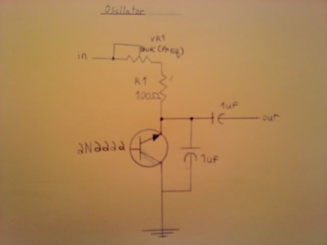
I recently come across a simple oscilator fx schematic,  now i understand that were i marked input is wrong its should be Vcc and is a power input. now i'm wondering where's the audio input go on this thing? any ideas? |
|
|
|
Post by ashcatlt on Apr 19, 2011 10:46:43 GMT -5
Dude I answered that question in the other thread.
It's an oscillator. It's not meant to have an audio input. It basically filters and amplifies its own self noise in an infinite feedback loop and puts out something resembling a sine wave.
|
|
|
|
Post by sbgodofmetal on Apr 19, 2011 11:45:50 GMT -5
Dude I answered that question in the other thread. It's an oscillator. It's not meant to have an audio input. It basically filters and amplifies its own self noise in an infinite feedback loop and puts out something resembling a sine wave. since you said its not meant to receive a signal and creates its own how the heck do you add it to an fx chain? would it have to be an x, y, input with1output? were the oscilator is y,? |
|
|
|
Post by sbgodofmetal on Apr 19, 2011 11:55:07 GMT -5
Now i'm thinking of it like a pedal, X&Y inputs with a single output. lets say for reference a booster effect, X is the guitar input for the booster and Y is the oscilator input to the boosters carrier signal. will this way work? i've not gotten a bread board to test it my self yet.
|
|
|
|
Post by ashcatlt on Apr 19, 2011 12:09:06 GMT -5
The oscillator thing I thought came out of our discussion re: the ring modulator thing. A ring modulator needs two inputs. Guitar would be one, and the oscillator would be the other. Most other effects expect just one audio input. I'm somewhat interested in what might happen if we used something like this oscillator in place of the DC power supply for a booster circuit, but haven't had a chance to breadboard it since you first brought it up. My suspicion is that it won't actually be particularly useful, but it might be cool, and won't hurt anything to try.
|
|
|
|
Post by sumgai on Apr 19, 2011 12:18:13 GMT -5
ash,
If it modulates the frequency, then it's a ring modulator, of sorts. Kinda not easy to do, but it can be done.
If it modulates the amplitude, then it's a tremolo device, pure and simple.
HTH
sumgai
|
|
|
|
Post by sbgodofmetal on Apr 19, 2011 13:04:33 GMT -5
which ever it is the desired output is a variable o0o0o0o0o0o, where the input signal is oooooooooooo. unlike a reverb or other similar fx where the output is a variable ooo0O0ooo0O0ooo. Am I right?
|
|
|
|
Post by sbgodofmetal on Apr 19, 2011 13:23:59 GMT -5
Also in another note i've run across another simple oscillator using cmos logic chips. Check those out at www.beavisaudio.com once there scroll down to cmos synthesizors. Sorry i can't post a direct link but this is where i've been getting alot of my most recent schemes from. Also check out blocks and pieces just a bit further down the list from the cmos thread, its from there that the psuedo ring mod, oscillator, electra distortion, as well as a few more i may or may not have posted as of yet came from. |
|
|
|
Post by sbgodofmetal on Apr 19, 2011 18:41:50 GMT -5
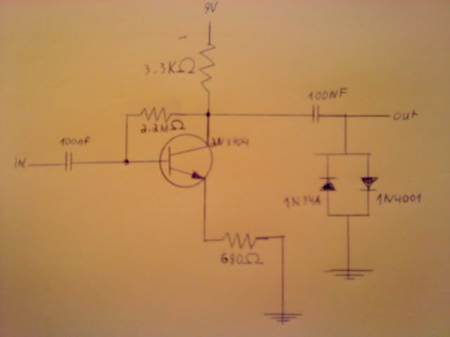
also on the electra distortion scheme  ash said in another thread that i could possibly replace the 680 resistor for a pot and cap for a level control. any suggestions on the pot and cap values for this circuit? |
|
|
|
Post by thetragichero on Apr 20, 2011 14:25:54 GMT -5
breadboard it. try 1k. try 2k. so on and so forth. make sure to have both A and B taper pots to see which works better for this application
|
|
|
|
Post by ijustwannastrat on Apr 20, 2011 14:41:24 GMT -5
breadboard it. try 1k. try 2k. so on and so forth. make sure to have both A and B taper pots to see which works better for this application But... but... that requires.... but....  ( ;D ) |
|
|
|
Post by sbgodofmetal on Apr 21, 2011 7:48:43 GMT -5
breadboard it. try 1k. try 2k. so on and so forth. make sure to have both A and B taper pots to see which works better for this application thanks for that tragic. I don't have a bread board as of yet but i'm expecting one within the next 2-3 weeks, but those values are very helpful and i thank you for that. |
|
|
|
Post by ashcatlt on Apr 21, 2011 11:30:27 GMT -5
That beginner project booster sets the gain the same way I suggested, so you might look there for inspiration. I don't know if you saw this thread over at DIYSB. I piped in there to see if we might get some answers from those folks, but didn't really get any specific values. A couple people mentioned putting a variable resistor in series at the input to control "gain". That way doesn't actually change the gain of the circuit, but accomplishes something similar be attenuating the input signal. You could get similar result using the volume pot on your guitar. |
|
|
|
Post by ashcatlt on Apr 21, 2011 11:46:38 GMT -5
ash, If it modulates the frequency, then it's a ring modulator, of sorts. Kinda not easy to do, but it can be done. If it modulates the amplitude, then it's a tremolo device, pure and simple. HTH sumgai Well, not according to my experience or the wiki definition of ring modulation. Ring modulation is amplitude modulation. It multiplies the amplitude of one input signal by another to produce its output. If one of these inputs runs at a low enough frequency (like below the audio band) it is tremolo. Of course, in the analog world, there's those series diodes in the signal path, which causes a sort of crossover distortion, so it's not really the best box to grab if you want just tremolo. I find that particular version of grit to be interesting for certain things... When both inputs are in the audio band, though, things start to get weird. It ends up creating side bands that sound like frequencies equal to X+Y and X-Y. The "musicality" of the output depends on the mathematical relationship between the two input frequencies. This gets particularly unusual when one or both of the inputs is very complex - not just one single frequencies but a bunch of frequencies mixed together - like a guitar playing chords or a drum beat. Did anybody listen to my little demonstration? |
|
|
|
Post by sumgai on Apr 21, 2011 15:08:49 GMT -5
ash, You're arguing both sides of the equation. First you quote a source that states, very incorrectly, that it's amplitude modulation: Well, not according to my experience or the wiki definition of ring modulation.
Ring modulation is amplitude modulation. It multiplies the amplitude of one input signal by another to produce its output. Yet further on, you state, correctly, that it's frequency modulation: Can't have it both ways, my friend. In point of fact, Wikipedia aside, the definition of tremolo is a variation of the amplitude, regardless of the frequency. (Usually, we take this to mean a continual and repetitive variation, at some non-varying rate. But the rate of variance can..... vary, that's according to Hoyle.) There's beaucoup history for this definition, all the way back to the beginning of radio communications, but we won't go there. (In case anyone is forgetting, at one time I was W7OLN. My current callsign is still on the books, so I can't publish that one, sorry.  ) Ring modulation is best defined as a complex interaction between a variety of frequencies, not just a pair of individual ones. X+Y and X-Y are just the start of the descriptors that take place therein. For the non-faint-of-heart, Google should be a good starting point. But if the above Wiki page comes up first, do try to forge beyond that one, please. HTH sumgai |
|
|
|
Post by JohnH on Apr 21, 2011 15:55:58 GMT -5
It needs some maths to explain it. Physically, the guts of a ring modulator seems to comprise a circuit that provides an output based on multiplying one input signal by another. So if we simplify the input down to just two pure harmonic tones, ie, sine waves, we can gain insight by looking at standard math results such as this, for the product of two sin functions, at two frequencies u/2Pi and v/2Pi:
Sin(u)sin(v) = ½ . [cos(u-v) – cos(u+v)]
So the output, on the right, has two components, one being at a frequency which is the sum of the two input frequencies, and the other at a frequency based on their difference.
Some simple results are:
If both inputs are equal, the difference signal is zero and the output is at twice the input frequency. Interesting, when considered musically because it is still a fully dynamic undistorted signal, but doubled up to one octave higher.
If one input is very slow, at sub audio frequency, you get two slightly different frequencies above and below the original tone, and when those signals become out of phase, you get a minimum overall volume, and when in phase, a maximum. That’s basically a tremolo, and tremolos have this frequency effect too, it comes from the maths.
If the two signals are both high frequency ie in the audio range, and there are many other harmoncs present too, then put very simply, the sums and the differences are doing all kinds of weird stuff.
Cheers
John
|
|