kiyiko
Rookie Solder Flinger

Posts: 9
Likes: 0
|
Post by kiyiko on May 6, 2011 19:13:12 GMT -5
Hi, I am Kiyiko ^_^ I have been working for the last few days to create a wire diagram, but I am kinda getting stuck with grounding problems, and crossed wires and generally messing up  What I have now is a guitar with a 5 way switch, a volume, and a tone. I would love to do all of this work without drilling any holes in my guitar, because its a nice one What I am looking to do is use a super 5 way switch, concentric pots for volume/tone, and a 4 position, 4 pole rotary dial for the different settings. This is what I wish to achieve in the end:  I think I have pretty solid beginnings in my diagram, but when I hit the coil tapping, and phasing, it seems to fall apart... This is what I have so far, that I am PRETTY sure works: 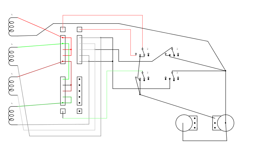 on the super switch I have the top left for half of the coils, the bottom left for the second half (there is always one coil turned on both of these poles in each position) The top right is the "coil return", which allows all 5 positions to be in series, rather than just the two humbuckers The bottom right is left open, probably for coil tapping purposes, but I have not quite figured it out yet The rotarty switch (I have it sepperated into it's 4 poles in the layout) should be 1: series, 2: parelell, 3: phase, 4: coil tapping If there is anyone here who can help me either finish this idea, or nudge me in the right direction, it would be greatly appreciated. edit: I should probably note that I am aware these might not be the IDEAL 5 positions, and it might be best sounding to change one of them, such as having a setting with all 4 pickups active or something.... (I don't know) I chose these 5 pairs of coils specifically to take only 2 poles on the super switch, leaving the the other two poles open for other things. Thought it might be wise to explain my reasoning for how those positions were made ^_^ Though, I actually just had an idea to arrange the coils on the super switch so that to get coiltapping, shut off one of the super switch poles... I might have to think on this... |
|
|
|
Post by sumgai on May 6, 2011 20:12:44 GMT -5
kiyiko, Hi, and  to the NutzHouse! I think I see where your problems are coming from. You've already worked out how to connect your pickups in series or in parallel, that's good. But let's look closer - they're always "in phase", no matter which coils or which pickups you've selected. However, when you want to select 'out of phase', you don't make any distinction between series or parallel. Since you have only one switch position, you will have to make a decision about this before we can help you any further. I was going to say that the same thing is true for selecting single coils, but then I realized that in this position, you never select more than one coil, so the bit about series versus parallel never comes up for discussion. However, having a duplicate selection (Bridge south coil) is a waste, and we'd like to suggest alternatives that might also appeal to you. Finally, we'd like you to consider that, depending on your pickups themselves, your combination choices may not be humbucking.... IOW, they may actually hum worse than one pickup by itself, or even just one coil by itself. This may or may not be of interest to you, but it is something to consider during the design stage (which is where we are right now). Let me close by 'warning' you that many members here will offer alternative wiring designs for you to think about. You may change your mind about your guitar when you've seen some of the stuff we've made here in The NutzHouse! ;D HTH sumgai |
|
kiyiko
Rookie Solder Flinger
Posts: 9
Likes: 0
|
Post by kiyiko on May 6, 2011 20:34:25 GMT -5
when you want to select 'out of phase', you don't make any distinction between series or parallel. Since you have only one switch position, you will have to make a decision about this before we can help you any further. Right now I dont quite know if I want "out of phase" to be series or parallel. I currently have accidentally modified ibanez HH wiring like this except I think one of my pickups was wired backwards because my 3rd and 4th position are out of phase, though I do like how it sounds. I am open to suggestions from any direction ^_^ I don't think series/parelell matters TOO much to me... I play bluesy and classical, and I usually always play on my parallel neck setting. I really love warmth in my tone if that helps at all. out of phase setting will not be a main part of my playing, but more of a novelty =] Let me close by 'warning' you that many members here will offer alternative wiring designs for you to think about. You may change your mind about your guitar when you've seen some of the stuff we've made here in The NutzHouse! ;D I am really open to suggestions at this point, I just don't want a simple vanilla layout, and I will not drill my guitar It's carved quilted maple, with recessed knobs, no good could come from messing with that, haha I have not ordered the parts yet, so the whole thing could change, but this seems to be the most intuitive and easy to "use" layout I could think of, but it has become a big logic puzzle that I am not good enough to solve <3 |
|
|
|
Post by sumgai on May 6, 2011 22:34:05 GMT -5
I am really open to suggestions at this point, I just don't want a simple vanilla layout, and I will not drill my guitar. OK, Nutz..... let her have it! ;D |
|
kiyiko
Rookie Solder Flinger
Posts: 9
Likes: 0
|
Post by kiyiko on May 7, 2011 0:53:55 GMT -5
Finally, we'd like you to consider that, depending on your pickups themselves, your combination choices may not be humbucking.... IOW, they may actually hum worse than one pickup by itself, or even just one coil by itself. Would you be able to explain this to me? I would be more specific, but this statement totally threw me off  Guitarnuts has taught me how humbuckers work! I am now educated, yay! So if I understand correctly, position 3 will be the only one that is not "humbucking", right? It's the only one that is not a north + south, am I correct? |
|
|
|
Post by sumgai on May 7, 2011 1:51:02 GMT -5
Guitarnuts has taught me how humbuckers work! I am now educated, yay! You mean something went right for a change? Man, how'd that happen?  Assuming the all-important fact that both pickups are identical, then yes, position 3 would probably hum pretty much as loud as any single coil, possibly worse. But keep in mind that if you use different pickups, even from the same company, position 3 may turn out to be hum-free, and positions 2 and 4 could be the bad ones, hum-wise. I'm a little surprised that no one else has pitched in yet...... come on, guys! sumgai |
|
kiyiko
Rookie Solder Flinger
Posts: 9
Likes: 0
|
Post by kiyiko on May 7, 2011 4:23:45 GMT -5
Assuming the all-important fact that both pickups are identical, then yes, position 3 would probably hum pretty much as loud as any single coil, possibly worse. =] I just checked with a bar magnet, and it seems like both humbuckers have the same polarity, wooo! |
|
|
|
Post by newey on May 7, 2011 9:21:00 GMT -5
kiyiko-
Hello and Welcome to G-Nutz2!
sumgai said:
I've been thinking- somewhere around here we had a similar idea way back when, but my search-fu is failing me at the moment.
Some things to consider, however. Complexity goes up dramatically when one insists on having "all possible combinations" or something close to that. And many combinations will sound similar.
In particular, having the ability to select either coil at the neck will probably not gave 2 distinct, useful tones, since the slight difference in spacing doesn't mean as much at the neck position. And all possible phase settings are not going to be useful, especially putting both coils of yur humbuckers out of phase with each other.
Your primary requirement is not altering the appearance of your guitar. 2 push/pulls could be used instead of the rotary. You could rethink the 5-way to give an OOP setting, and lose the non-humcancelling single coil combo, one p/p could be used for series/parallel options and the other p/p to split both pickups to single coils.
This wouldn't give you all of what you want but is a good bit simpler to do. I'm still staring at your original idea, I'm not ruling that out, mind you, just trying to see how you could get that all to work.
|
|
|
|
Post by JFrankParnell on May 7, 2011 10:26:03 GMT -5
|
|
|
|
Post by JohnH on May 7, 2011 15:57:06 GMT -5
Hi kiyiko. What you describe can definitely be done, using the parts that you have identified, including the rotary.
There are good points made above, including the issue that some of your settings will be non humcancelling. You can position the pickups to control which will be humcancelling. Typically, in series or parallel mode, if 1, 2, 4 and 5 are humcancelling, then 3 would not be.
Next issue is, I agree that the rotary would need 4 poles. With 4 positions, this is a double deck switch. These are easy enough to obtain from an electronics suppler such as mouser (with up to 6 positions), but note that they are deeper than single deck switches. If this proves to be a problem, you might consider losing the out of phase setting and just have three positions, which could be a standard 4-pole 3 position rotary, single deck switch. If you take that step however, you could then alternatively do it with two pots with push pull switches, one to set series/parallel and the other to coil cut.
How to think about the wiring? and I applogise if you have already had a similar thoughts:
I think one way of making all this work is to note that you never want to select more than 2 out of the 4 coils. So you could use the 4 poles of your 5-way switch to select each end of the two coils that you want to use in each setting. 8 wires from the real coils go into the 5-way, and from the poles, 4 wires come out, being hot and cold of the coils that you want. That reduces the problem to just two 'virtual coils', 1 and 2. Take coil 1, and put it through two poles of the rotary, acting as a phase switch. Then after that, the last two poles of the rotary are wired to do series/single/parallel, and the job is done!
John
|
|
kiyiko
Rookie Solder Flinger
Posts: 9
Likes: 0
|
Post by kiyiko on May 7, 2011 17:11:54 GMT -5
I think one way of making all this work is to note that you never want to select more than 2 out of the 4 coils. So you could use the 4 poles of your 5-way switch to select each end of the two coils that you want to use in each setting. This was actually the idea I had about a week ago, but then I ran into the problem of being able to make each of the 5 positions series. I figured if I squished all 5 positions into two poles, it would give me a lot more room to "play", leaving the other two poles open =] I think the only thing I really sacrificed for this idea was a "all coils on" position. That's how I got where I am now. one question I had is: with such a complex idea, does noise become more and more of an issue? I kinda have it stuck in my mind that more complex circuits become harder to make silent, is this true? |
|
|
|
Post by JohnH on May 7, 2011 17:41:40 GMT -5
one question I had is: with such a complex idea, does noise become more and more of an issue? I kinda have it stuck in my mind that more complex circuits become harder to make silent, is this true? It should be Ok if you wire it neatly. Most of the complexity is just around the switches lugs, which are only short wires. A shielded cavity and pickguard is helpful. The other things that affect noise are the non-humcancelling combos, and if you have coils which are inactive but still connected to the hot output (but disconnected from ground), I believe that can add noise. That is open for discussion however. As for the scheme - heres a really quick rough sketch or what i meant without pots, and without the full 5-way wiring, but showing the 4 poles of the rotary:  In single coil mode, it cuts to just 'coil 2', so when you wire up the 5 way, make sure the poles for 'coil 2' are assigned to select whichever actual coil you want in each position. cheers John |
|
kiyiko
Rookie Solder Flinger
Posts: 9
Likes: 0
|
Post by kiyiko on May 8, 2011 1:35:49 GMT -5
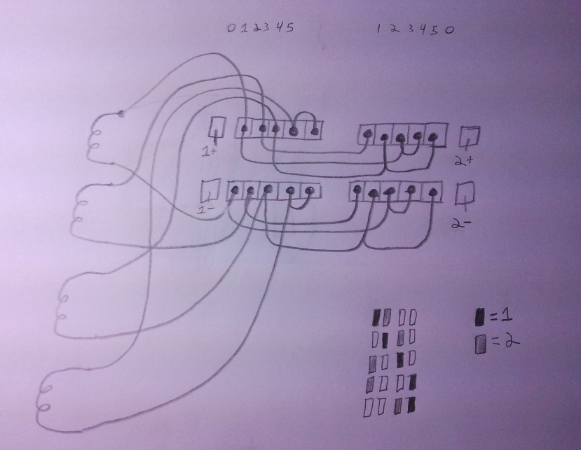 Is this what you had in mind for using the super switch to create two "virtual coils"? (also re-arranged to put all of the "single coils" on the same pole.)((just to make clear, the bottom poles are a mirror or the top poles, just using the coil returns, rather than the leads, is this what was intended?)) Seems a lot more graceful than anything I had written down through the last week of busting my brain around this whole idea >< I really like this idea. I am so glad I was told about this place I hope I am understanding what you are advising, and applying the idea properly! |
|
|
|
Post by JohnH on May 8, 2011 1:49:15 GMT -5
Nice! yes you have it worked out. Only thing between your diagram and mine is that the single coil selections that you want, you are calling "coil 1", but I am calling them "coil 2". keep your diagram as you have it, and keep the wiring on mine, just swap the coil1 and coil 2 labels on mine.
Cool
John
|
|
kiyiko
Rookie Solder Flinger
Posts: 9
Likes: 0
|
Post by kiyiko on May 8, 2011 2:06:24 GMT -5
I am feeling good about this now! Would you be able to give me a few little pointers about how to do some of the grounds? Last time I attempted wiring my guitar I made this mess: gyazo.com/87462bc623124a3c0e1645120b016c17.pngI seem to have trouble dealing with the the mass of wires that accumulate on the switch, due to all the wires my pickups have Most of my issue comes from the ground wires, and the shield. I could not figure out a good way to make it "clean" I think it might be a lot easier this time around as all the leads/returns seem to go to a lug, which leave only the braided shield. do I just twist those together with a ground wire, solder it, and tape it off? I was also wondering if you know the proper way to ground the rotary switch? do they often come with a ground tab or something like that? |
|
|
|
Post by JohnH on May 8, 2011 2:50:35 GMT -5
I think the neatest way to wire up a complex scheme is:
1. Draw a diagram of the actual lug positions and wiring
2. Make a cardboard template of the hole positions, to mount the controls temporarily
3. Wire up the connections within each switch, you can use bare wire for this if you wish, so long as there are clear gaps between
4. Use insulated flexible wire for connections between the main controls
5. Bare wire is also often ok for ground wires, unless there is risk that it may move to touch something
6. If you have a foil screen behind the pick guard, then if you ground the pots, then other switches will get grounded by contact with the foil – not for signals but just for screening. Or, if not and there’s no lug, a wire to a washer around the shaft can be grounded
7. Sometimes I have a bare ground wire between pots, then attach the braids from the pickups along it, if that is more convenient than trying to solder all grounds to one place
8. Get as much wiring done as possible out of the guitar, then put the harness in and attach the pickup wires
9. Don’t forget to ground the bridge
cheers
John
|
|
kiyiko
Rookie Solder Flinger
Posts: 9
Likes: 0
|
Post by kiyiko on May 8, 2011 3:03:04 GMT -5
Thank you ^^ I really appreciate all the help you guys have been |
|
|
|
Post by newey on May 8, 2011 7:19:15 GMT -5
Yes, pretty much. You should pick a definite grounding point to collect all the grounds. I usually use a screw into the side of the cavity. This is then connected to the outjack negative.
It's probably not necessary to do so. If you have shielded the cavity, the shaft should be grounded through your shielding.
|
|
kiyiko
Rookie Solder Flinger
Posts: 9
Likes: 0
|
Post by kiyiko on May 8, 2011 14:22:10 GMT -5
It's probably not necessary to do so. If you have shielded the cavity, the shaft should be grounded through your shielding. It's not shielded right now, but I will probably attempt to when I do this. ^_^ |
|


