|
|
Post by poolhalljunkie13 on Jan 12, 2012 7:33:06 GMT -5
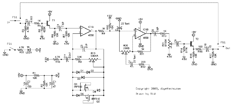
Hello. This is my first post. I googled for forums to ask my question and thought this was the best one so hopefully someone can help me. For starters this is the Tube Screamer PCB i'm using so you can put your eyes on it. diyeffects.com/products/Fproduct-1.jpgWhat I want to do is put in a switch so I can change between standard clipping (D1, D3) or asymmetrical clipping (D1,2,3) and if possible switch between 3 options and add mosfet clipping (D4,D5,Q1,Q2) or 4 and also add LED clipping (D4,D5,Q1,Q2). So either switch between 2, 3 or all 4 options. If it's possible to do more than 2. IDK. Can someone describe to me the easiest way to do this and which switch to use. I'm kinda new at this. I know my way around a circuit board but Im no pro. I saw a way of soldering the actual diodes to the lugs on the switch but Im not sure the correct way to do this or if it will work. So if someone can help me out that would be amazing. I've been thinking about this for days now trying to figure it out myself and I have finally caved in. I hope to stick around here as well as it looks to be a very informative forum with lots of info. Thanks guys. Robert |
|
|
|
Post by asmith on Jan 12, 2012 9:48:00 GMT -5
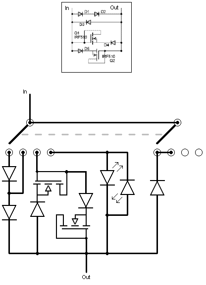
Hi Robert. Welcome to GN2. I took the liberty of taking a look at the instruction manual for the schematic - it's on the last page if anybody wants to print it out. I've condensed it down to this so we can all have a gander. Jeweller's glasses on:  What you want is absolutely possible. You could do it with a Two-Pole, Four-Throw (2P4T) rotary switch. Here's a Mouser link. Stick another knob on top of the switch, and you can make it blend in with your other controls too. Here's how:  I don't know how versed you are at reading rough schematics like that? If you need a wiring diagram instead, just ask. ~!~!~!~!~!~!~!~!~!~!~ Further NutzIf you're prepared to buy another diode you can do it with just a One-Pole, Four-Throw rotary switch. You can turn the clipping circuit off for just the boost by using a Two-Pole, Five-Throw rotary switch - very simple, and recommended. If you are prepared to go all-out nutz on this and do a buttload of soldering, you can even have a ton of clipping options, like this: - Symmetric Diodes
- Assymetric Diodes
- MosFETs & Diodes
- LEDs
Symmetric Diodes in parallel with MosFETs & Diodes
- Symmetric Diodes in series with MosFETs & Diodes
Assymmetric Diodes in parallel with MosFETs & Diodes
- Assymmetric Diodes in series with MosFETs & Diodes
Symmetric Diodes in parallel with LEDs
- Symmetric Diodes in series with LEDs
Assymmetric Diodes in parallel with LEDs
- Assymmetric Diodes in series with LEDs
MosFETs & Didoes in parallel with LEDs
- MosFETs & Didoes in series with LEDs
Everything in parallel
- Everything in series
MosFETS & Diodes in series with Symmetric Diodes, in parallel with LEDs
- If you're still reading this, I'm impressed
|
|
|
|
Post by poolhalljunkie13 on Jan 12, 2012 10:05:07 GMT -5
Wow thank you for your in depth reply. Unfortunatly I cant fully read schematics yet. If you could draw it out in simple terms that would be great.
Also being that you described doing all 4 could you describe just doing the first 2 and which switch I would use?
Once again thank you so much for taking the time to help me out. I really do appreciate it.
Robert
|
|
|
|
Post by ashcatlt on Jan 12, 2012 10:28:30 GMT -5
That list of options is impressive. Of course, the "parallel" options are pretty much useless. Whichever one has the lowest forward drop will turn on first, and the other won't ever get to do anything. I guess if you had two asymmetric pairs in parallel you might get one from one pair on upswings and one from the other on downswings...
I'd also want to compare forward drops between the various combinations. For example two silicon diodes in series is about the same thing as an LED.
|
|
|
|
Post by asmith on Jan 12, 2012 10:35:35 GMT -5
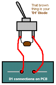
If you just want to swap between symmetrical and assymmetrical clipping, piece of cake. Wire it up like this - excuse the MSPaint.  That's a single-pole, single-throw, on/off switch. EDIT:Of course, the "parallel" options are pretty much useless. Whichever one has the lowest forward drop will turn on first, and the other won't ever get to do anything. Facepalm. |
|
|
|
Post by poolhalljunkie13 on Jan 12, 2012 11:11:21 GMT -5
Wow that does look easy. So wire it to D1 and put my D1 diode on the switch? Do I need to put my diode on D2? Or wire it up normal with D1 and D3 and jumper D2? Which is symmetrical. Asymmetrical is obviously adding the D2 diode so would I add the D2 too?
Thanks again for your help because you are making this really easy for me.
|
|
|
|
Post by asmith on Jan 12, 2012 15:03:02 GMT -5
No troubles.
Wire up D2 and D3 exactly like you would anyway.
What the switch above does is bypass D1. In a nutshell, "asymmetric" clipping is caused by differing properties in diodes. It's not that the presence of D2 makes it asymmetric - it's that D1 plus D2 is a different amount (more) of that diodey goodness than D3.
When D1 is bypassed, the signal heads straight to D2. D1 is taken out of the circuit. You've just got D2 = D3. Equal. Symmetric.
So if you feel more comfortable doing this a/symmetric switch with D2, you could just swap wherever it says "D1" in that picture with "D2."
Don't take me to any scientific conventions and ask me to repeat that. I hope it gets the general gist across though. Questions / queries / worries / woes, make a noise and we'll help.
Cheers
|
|
|
|
Post by poolhalljunkie13 on Jan 12, 2012 15:34:26 GMT -5
Makes complete sense. Thank you so much.
|
|
|
|
Post by reTrEaD on Jan 13, 2012 16:32:50 GMT -5
Of course, the "parallel" options are pretty much useless. Whichever one has the lowest forward drop will turn on first, and the other won't ever get to do anything. Very true, for the most part. Definitely true when stacking multiples of the same type of device. But I think the FETs don't snap "on" as abruptly. So there could be a little bit of difference with them in parallel with multiple diodes. |
|