|
|
Post by axekicker on Feb 28, 2012 18:26:53 GMT -5
DPDT SWITCHES: I’m having a hit and miss relationship with these, and I’m not sure if it’s me or them. I’m getting mine from Radio Shack, and they look/feel okay, but… are they crap? (I have success with their momentary switches). And this is a dumb one, but how do I tell north from south? How do I know which lugs do what? And when the diagram calls for the ground and braided wire from a 4-lead pup to be attached to a lug, can’t I just ground these wires somewhere else since there’s yet another ground wire specifically for the switch? The lug is too damn small to hold both.
PICKUP WIRES: All the manufacturers use the same colors, but assign different polarities, etc. Yet, the white and red are always together. Can I assume this is North and South every time? Also, because I keep having to re-wire my stuff due to mistakes, my leads are getting shorter and shorter. My idea is to solder them to heavier 26 gauge hookup wire for sturdier connections. Is this ok? I know it’s not ideal, but I’m about out of options here until my skills improve.
LEVER SWITCHES: I use Fender 5 and 3-ways, yet nobody uses Fender switches In their diagrams. I don’t get it. I assume the spring should always be facing outward, yes? And should it be grounded? Some diagrams call for a separate wire to ground the switch and others do not. Why not?
WIRES: Why is using that braided wire a “best practice” when wiring an output jack? I can’t stand the stuff, and it always falls apart in my hands when I attempt to separate it. I feel like Lenny trying to groom a mouse ; I kill it every time. Then, if I get it done, the wires seem to always connect when I attach the pickguard and it shorts. Can I not just use two strands of 24 or 26 gauge wire and call it a day?
INDUCTOR: What does this do, and why can’t I find them anywhere? I know it’s used with a ES-335 varitone, but why? What kind should work for that application? I saw some on eBay, but I have no idea if they're the kind I need.
OK, thanks. I’m looking forward to posting my latest Frankensteins (unless they destroy me first).
|
|
|
|
Post by reTrEaD on Feb 28, 2012 19:57:13 GMT -5
DPDT SWITCHES: I�m having a hit and miss relationship with these, and I�m not sure if it�s me or them. I�m getting mine from Radio Shack, and they look/feel okay, but� are they crap? (I have success with their momentary switches). Not "crap", but I have definitely seen better minitoggles than the ones from Rat Shack. And this is a dumb one, but how do I tell north from south? North or south on a switch? What?  How do I know which lugs do what? DPDT minitoggle have their lugs arranged in a 2x3 pattern. If we arbitrarily label them, it will be easier to explain what happens: A B C D E F - The left and right sides are electrically separate from each other. - When the toggle is in the down position, C is connected to A, D is connected to B. When the toggle is in the up position, C is connected E, D is connected to F. And when the diagram calls for the ground and braided wire from a 4-lead pup to be attached to a lug, can�t I just ground these wires somewhere else since there�s yet another ground wire specifically for the switch? The lug is too damn small to hold both. Yes, you can. PICKUP WIRES: All the manufacturers use the same colors, but assign different polarities, etc. No. Not all manufacturers use Red, Black, White, and Green. Some use Blue or Yellow or Brown or even Pink! www.skguitar.com/SKGS/sk/Pickup%20color%20codes.htmYet, the white and red are always together. No. Red and white are joined together as a series link on Seymour Duncan pickups. BLACK and white are joined together and a series link on DiMarzio pickups. Can I assume this is North and South every time? Absolutely not. Also, because I keep having to re-wire my stuff due to mistakes, my leads are getting shorter and shorter. My idea is to solder them to heavier 26 gauge hookup wire for sturdier connections. Is this ok? I know it�s not ideal, but I�m about out of options here until my skills improve. FAR from ideal. But do what you must. And make sure the joints where the pickup wires are soldered to the extensions are properly insulated. Heat shrink tubing works well. LEVER SWITCHES: I use Fender 5 and 3-ways, yet nobody uses Fender switches In their diagrams. I don�t get it. Not true. Some people DO use Fender switches in their diagrams. Others use the replacement switches that are similar, but use a slightly different lug arrangement. Others use 8lug import switches, like on a Squier or Ibanez. Others use 7lug import switches. Others use Megaswitch T (or Telecaster) or Megaswitch S (for Strat) Others use 4P5T superswitches or Megaswitch M. People create their drawings around the switch THEY are using. This won't always be the same as the switch YOU prefer to use. Often, you can adapt their wiring to your switch. But in the case of 4P5T switches, you won't be able to adapt the wiring to a conventional "Strat" switch. I assume the spring should always be facing outward, yes? Electrically, the two halves of a Fender 5way are mirrored. It won't matter electrically which direction the switch is oriented. What will matter how much clearance you have between the lugs and the wall of the control cavity. And should it be grounded? Some diagrams call for a separate wire to ground the switch and others do not. Why not? Better if the frame of the switch is grounded, but not absolutely necessary. The frame can be connected via the pickguard shielding rather than directly wired to ground. WIRES: Why is using that braided wire a �best practice� when wiring an output jack? Because the outer braiding blocks some of the hum from getting on the inner conductor, which carries the signal. I can�t stand the stuff, and it always falls apart in my hands when I attempt to separate it. I feel like Lenny trying to groom a mouse ; I kill it every time. Then, if I get it done, the wires seem to always connect when I attach the pickguard and it shorts. Solution: Plan ahead and improve your technique. OR... Can I not just use two strands of 24 or 26 gauge wire and call it a day? Of course you can. You might get a tiny bit more hum, but your guitar won't blow up or anything. Fender uses two wires rather than a shielded cable. INDUCTOR: What does this do, Inductors are the complement of capacitors. Capacitors block DC and their reactance decreases with frequency. Inductors pass DC and their reactance increases with frequency. and why can�t I find them anywhere? They aren't as common as capacitors. But they can be found if you search long enough. (No, I won't search for you.) I know it�s used with a ES-335 varitone, but why? An inductor wired in series with a capacitor, forms a mid-cut filter. What kind should work for that application? I see two paths to success: 1 - Research the value of the inductor and capacitors used in the Gibson Varitone. Locate an inductor of the correct value. 2 - Get an inductor(s) of unknown value(s) and experiment with capacitors of different sizes. You may find combinations that puts the resonant frequency of the mid-cut network where it sounds good to you. I saw some on eBay, but I have no idea if they're the kind I need. I don't know either. |
|
|
|
Post by darkavenger on Feb 28, 2012 20:40:07 GMT -5
Yea... inductors. Hmm... I've never come across any sources from brief searches, probably just missing them or something..? I've heard of people making their own though with 22 gauge wire...
It's something I'd like to play around with but not if I can't find them easily.
Also, if you know the polarity of one magnet you can find the polarity of another by watching them interact. That's what I do. If you have a compass that would tell you too, but don't use the one on your smartphone!
Shielding and braided wires and all of that is to reduce interference, which causes hum. Not absolutely necessary but greatly recommended. The better the shielding, the less hum you'll get.
|
|
|
|
Post by newey on Feb 28, 2012 23:19:46 GMT -5
Why all this gnashing of teeth over inductors? Mouser lists over 33,000 different types. Filter to find the values and style you need. A picture works better, I think: 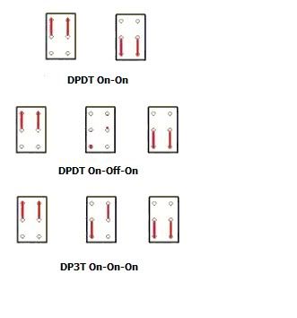 Here's the skinny on all three commonly-seen DPDT switches, showing the internal connections. Note that the position of the toggle lever actuator will always be opposite of the lugs which are connected. For example, the On-On diagram on the right side shows the lower lugs connected internally; the lever would be "up" in this position. Also note that the On-On and On-Off-On switches are both symmetric to rotation- there is no "north" or "south" as you put it. But the third one, the On-On-On version, is not symmetric- it does matter which way is "up". For those, test with a meter and mark the switch so you know which way it goes. The third one is called either an On-On-On or a "Center On" switch. I labelled it as a "DP3T", which is what we often call them around here. You'll see that description used in posts, so that we all know we're talking about a three-position toggle. To be technical, however, it's really not a three-throw switch, it's a DPDT just like the others. This is because a "throw" implies that a separate set of electrical connections is being made- and the center position on these switches doesn't make any "new" connections, it just rearranges the ones already made. So, armed with that knowledge, DPDT switches should no longer be a mystery . . . |
|
|
|
Post by reTrEaD on Feb 28, 2012 23:49:54 GMT -5
A picture works better, I think: Yes!  But the third one, the On-On-On version, is not symmetric- it does matter which way is "up". For those, test with a meter and mark the switch so you know which way it goes. The third one is not symmetric across the horizontal or vertical axis. But it IS symmetric, rotated 180 degrees. Thus it matters not whether the switch is oriented as shown or rotated 180 degrees. The lower left and upper right will still be connected in the toggle-center position.  Why all this gnashing of teeth over inductors? Mouser lists over 33,000 different types. Filter to find the values and style you need. Unlikely to find an inductor of a useable physical size in there. I'd guess the value for a varitone to be more that 1H but less than 20H. In values that large, Mouser will probably only have power inductors intended for PS filtering. Physically large shiz. More likely to have success using the primary winding of a miniature interstage transformer or modem transformer. But you'd have to buy a few different models and measure the inductance. Or just experiment to find what sounds good. |
|
|
|
Post by darkavenger on Feb 29, 2012 0:19:24 GMT -5
Mouser is a bit scary sometime, for those of us who aren't experts in electronics. I did find the inductor I was looking for though, oddly enough. It's funny because mouser was one of the first places I looked... I really missed it somehow. um... don't ask.
|
|
|
|
Post by axekicker on Mar 2, 2012 13:17:20 GMT -5
I was wondering if there's a proper orientation, but your diagram makes it clear. I'm tired of installing components without knowing how they work.
OK, it's the series link, got it. So when you spit them, you go into parallel? And when you link them together on a DPDT, you turn them off? Can I use a SPST switch for this?
Yes, I'm tubing it. It bugs me that I can't get this right, so I'll practice more. I've discovered that very short exposed wire is better than more exposed wire. I guess I was incorrectly assuming that more exposed wire would somehow give me a stronger connection with more signal blah blah. Instead, it just increases the chances of shorting.
Yeah, I have yet to come across a lug arrangement that matches my switches.
These diagrams are hard to come by. I found one on Artec's site. But now I'm using a multimeter to figure things out. Yea for me.
Yeah, I'm not there yet. I want to try the diagram on Alexplorer's site where you get a ridiculous combination of sounds from two hum buckers hooked up to two 12-position rotary switches. This will be the project that 5150s me.
I didn't know they were mirrored. That's how it always looks, but I wasn't sure.
OK. Another question: I've been working on a Talman now for THREE MONTHS with THREE switches (series/split/parallel, split, and phase) and one mini pot, a varitone, and a killswitch. It's a lot jammed into a tiny cavity even post routing. Every time I press the pick guard down into the cavity, everything shorts and stops working. I've re-wired everything now with 26 gauge, made sure there's no exposed wire thanks to iron burns. Obviously something is touching something. Could it be the copper shielding? Or should I shield around everything once it's in place? Can I replace the coil cut DPDT with a smaller SPST?
I see. But whenever I do it this way my hot invariably touches my ground at the pot or the jack. I am going to try tubing the ends from now on and see if that works.
Big time. With the Talman, I drilled an extra hole by mistake and so I'm plugging it with a switch. I could've used one on/on/on to work both pups, but...
I didn't know that. In the StewMac video "How to wire a Strat," Erlewine uses a shielded cable.
Thanks for that. I didn't know it was for mid cut.
Can I send you a link to what I found?
Thanks for taking the time. I will post a pic of the Talman once it's done.
|
|
|
|
Post by axekicker on Mar 2, 2012 13:21:29 GMT -5
A-HA! That's what was happening to my hookup. My on/on/on was only putting out two sounds, not three. I had it wired upside down. I've got it working now but wasn't sure if I just used better wire or better soldering or what. Thanks for clarifying!
|
|
|
|
Post by axekicker on Mar 2, 2012 13:24:28 GMT -5
|
|
|
|
Post by reTrEaD on Mar 2, 2012 14:47:09 GMT -5
OK, it's the series link, got it. So when you spit them, you go into parallel? And when you link them together on a DPDT, you turn them off? Can I use a SPST switch for this? The term "split" means to use only one of the two coils. So the sound is similar to a single coil pickup. What can you accomplish with a SPST? You can wire the two coils in series, then shunt one when the SPST is in the on position. This will give you series/split. Or you can wire the two coils in parallel and disconnect one coil when the SPST is in the off position. This will give you parallel/split. But you can't do series/parallel with a SPST. You'll need a DPDT for that. Yes, I'm tubing it. It bugs me that I can't get this right, so I'll practice more. I've discovered that very short exposed wire is better than more exposed wire. I guess I was incorrectly assuming that more exposed wire would somehow give me a stronger connection with more signal blah blah. Instead, it just increases the chances of shorting. Shrink tubing is a bit tricky when you're first learning to use it. Sharp edges in the joint will break through when the tubing shrinks. With a little practice, you'll get it right. OK. Another question: I've been working on a Talman now for THREE MONTHS with THREE switches (series/split/parallel, split, and phase) and one mini pot, a varitone, and a killswitch. It's a lot jammed into a tiny cavity even post routing. Every time I press the pick guard down into the cavity, everything shorts and stops working. I've re-wired everything now with 26 gauge, made sure there's no exposed wire thanks to iron burns. Obviously something is touching something. Could it be the copper shielding? Or should I shield around everything once it's in place? The most obvious way to avoid shorts is to have enough clearance between bare connections and ground. But sometimes there just isn't enough space. In that case, heatshrink tubing or tape covering the connections can help. Or prevent exposed connections from touching the shielding foil by putting a layer of tape on the foil itself. Can I replace the coil cut DPDT with a smaller SPST? Yes. Can I send you a link to what I found? Yes. Those have a value of 10uH, not 10H. So their inductance is about a million times lower than what you need. |
|
|
|
Post by axekicker on Mar 2, 2012 17:53:42 GMT -5
What do you mean by "shunt." How do I shunt? I notice that if I just want a split on a DPDT, I'm only wiring half the switch (series leads to middle lug and ground to the lug beneath). So I would just do the same on an SPST, correct?
|
|
|
|
Post by reTrEaD on Mar 2, 2012 19:09:05 GMT -5
What do you mean by "shunt." How do I shunt? I notice that if I just want a split on a DPDT, I'm only wiring half the switch (series leads to middle lug and ground to the lug beneath). So I would just do the same on an SPST, correct? Yes. And the answer to the first question is in your later question. Connecting the series link to ground (via the switch) shunts one of the coils. |
|
|
|
Post by newey on Mar 2, 2012 19:44:18 GMT -5
Yes. By "shunt", RT is referring to the fact that, by grounding out the series junction between the two coils, you are shunting the coil that has its other end connected to signal return ("Ground", if you prefer).
We'll call that coil the "lower" coil in the series chain. Using SD colors, that would be the green/red coil, with the green wired to "ground".
The other coil, the "top" coil we'll say, has its black wire going to output, known as "signal send". The other end, the white wire, joins the red wire to make the series junction.
We can thus trace the signal "flow" through the two coils. Starting from the signal return, it goes through the green wire, through the lower coil, through the red wire to the series junction, through the white wire to the top coil, through that coil and out the black wire to the V, T switches, whatever, eventually getting to the output jack "hot" connection.
And, since this is AC, the signal flow also goes the opposite way as well- we could just as easily start our tracing from the black wire, going in the opposite direction.
Now, let's examine what happens when we connect that "series junction" to the switch common lug, and ground one of the other lugs. When the switch common is not connected to ground, our series junction functions just as described above, and we hear both coils in series, the classic HB sound.
But when we flip the switch, connecting the commons to "ground", look what happens to our signal flow. The lower coil is now connected to "ground" at both ends, "shorting" or "shunting" the coil. We don't hear that coil, since it's just connected back to itself in a loop.
The "top" coil, however, still has its black wire connected to output "hot", and now the other end, the white wire, is connected to "ground" through the switch. That coil now makes a complete circuit (through a cable to the amp, of course- it doesn't make a circuit until you plug it in!). We hear the "top" coil only; we can say we have "split" the HB to a single coil.
But suppose we want not the top coil to be split, but the bottom coil instead. How? Easy enough, instead of grounding the series junction with the switch, we connect it to the "hot" output. Now, the opposite happens, the black and white wires are connected together, shunting the "top" coil. The bottom coil now has its red wire connected to the hot via the switch; the other end is permanently connected to "ground", so we hear that coil instead.
There is another way to accomplish the same thing, by wiring the pickup "inside out", so that black and green form the series junction. The result is the same, you split the opposite coil.
If you still have difficulty "seeing" what is happening based on my verbal description, try drawing it out and tracing the signal, and all should be clear.
Also note that you will often see coil splits referred to as a "coil tap" (well, you'll see that terminology elsewhere- not here!). This is a misnomer, and a confusing one. "Tapping" a coil technically means running a wire off the midpoint (or some other fraction) of the coil's windings, so that we are only using one-half (or other fraction) of the full coil. This can be done on a single coil, as well as on one or both coils of a humbucker.
It's a confusing term because, back in the day, this was in fact done by some manufacturers.
|
|
|
|
Post by dannyhill on Jul 19, 2012 5:14:03 GMT -5
Hi guys, You seem to be using DPDT on-on-on switches of 'type D' as seen here: www.1728.org/guitar.htmThese are supposed to be the more unusual variant of 'type C' which is what I am looking for but for the life of me cannot find them. I wanted to attach two tone caps so I get either cap 1, both in parallel (sum of both), or cap2. Where can these be found? Alternatively, instead of using them to join each of the two end poles I could join one leg of each and attach to the tone pot lug and then either add jumpers across each the switch or diagonally criss-cross either the LHS with centre lugs or RHS and centre lugs. Would that work? Or should I be opening a new thread? Cheers, DH |
|
|
|
Post by reTrEaD on Jul 19, 2012 5:57:32 GMT -5
Or should I be opening a new thread? You could have, Danny. But this works okay too. Yep. These are supposed to be the more unusual variant of 'type C' which is what I am looking for but for the life of me cannot find them. There are some interesting and useful things on that site, but that bit of info is just plain wrong. You can't find 'type C' because to the best of my knowledge, no one makes it. A standard Gibson toggle act like half (one pole) of a 'type C'. But that's as close as you get. I wanted to attach two tone caps so I get either cap 1, both in parallel (sum of both), or cap2. Where can these be found? Alternatively, instead of using them to join each of the two end poles I could join one leg of each and attach to the tone pot lug and then either add jumpers across each the switch or diagonally criss-cross either the LHS with centre lugs or RHS and centre lugs. Would that work? Since you only need one pole to accomplish this task, you can wire the DPDT on-on-on to get where you need to go. Put a jumper between the two poles (center lugs). Then use the upper right and lower left throws. This functions just like a Gibson toggle. A, Both, B. Cheers! |
|
|
|
Post by dannyhill on Jul 19, 2012 6:41:18 GMT -5
Excellent! Thanks for that ReTread. Incidentally, I also had in mind to use a 4PDT/4P3T on on on for switching simultaneously the two separate pairs of cap, one for a parallel wiring of pups and one for series wiring of pups. I would then jumper the two center lugs on each side of the throw. I prefer this than using two separate DPDT on on on toggles as I only have room for two more toggle switches and wanted one to be for a strangle. Are 4PDT/4P3T on on on toggles common? I have only seen some pricey ones on Ebay with different toggle tops to the usual toggles. Cheers, DH |
|
|
|
Post by reTrEaD on Jul 19, 2012 7:19:00 GMT -5
4PDT on-on-on are fairly common, but not cheap. Expect to pay $20~30..
|
|
|
|
Post by dannyhill on Jul 19, 2012 9:39:09 GMT -5
I would have to double the insurance coverage on the guitar then  By the way I usually connect my caps (tone and strangle) with DPDTs which means the caps are connected in a bypass as supposed to a shunt. This means when I switch from one to the other...poptastic! I could put a 1MOhm resistor to ground on the side closer to ground. Or should I always wire them so they have one side wired together i.e. configure in SPDT instead of DPDT? Thanks! D |
|
|
|
Post by newey on Jul 19, 2012 16:52:56 GMT -5
Our member wolf, who runs 1728.com and ChrisK had an ongoing debate years ago about wolf's "type C" On-On-On switch. It basically came down to Chris daring wolf to "Find one!". Wolf was unable to do so. So, I think RT is right on that, ain't no such animal. Of course, any switch manufacturer would be happy to make some up for you, provided that you're prepared to order a quantity somewhere north of 10K of the things . . . . RT's got you on the path with a DPDT. Here's a version using a simplified SPDT On-Off-On- courtesy of ChrisK:  SP On-Off-On switches are more available, and cheaper, so you may want to consider that option. |
|
|
|
Post by dannyhill on Jul 20, 2012 11:27:09 GMT -5
Thanks Newey!
Final question :-)
I seem to have a problem with popping in Gibson switches, strangle switches and tone cap switching.
What is the general rule to avoid it without resorting to MOhm resistors?
For example if I wire a SPDT to switch a cap in/out of series from 3 way gibson pup selector to hot on jack should the jack connection go on the centre lug or one of the outer lugs? My intuition says the latter, that way the 3 way connection, which if you trace all the way back to ground, will always be in the circuit.
?
|
|
|
|
Post by newey on Jul 20, 2012 21:39:58 GMT -5
I'm not following what you mean there. The center lug of a Gibby toggle is the common lug, you have to wire that to output to be able to select the pickups.
|
|
|
|
Post by dannyhill on Jul 21, 2012 9:04:25 GMT -5
You can switch a cap in and out between it and the jack. With a 0.003uF you get the 'strangle' or bass cut.
The lugs I referred to were for the SPDT.
Any clearer?
|
|
|
|
Post by ashcatlt on Jul 21, 2012 18:29:54 GMT -5
Why not just shunt the cap when you don't want it?
|
|
|
|
Post by newey on Jul 21, 2012 22:38:44 GMT -5
Yes- if the question is choosing between a diagram like the first one and the second one (with the second one shunting the cap, as Ashcatlt suggests). I wouldn't think there would be a difference either way, unless, as Ash seems to be suggesting, the shunt version is better to avoid the "pop". I'm unsure on that score. 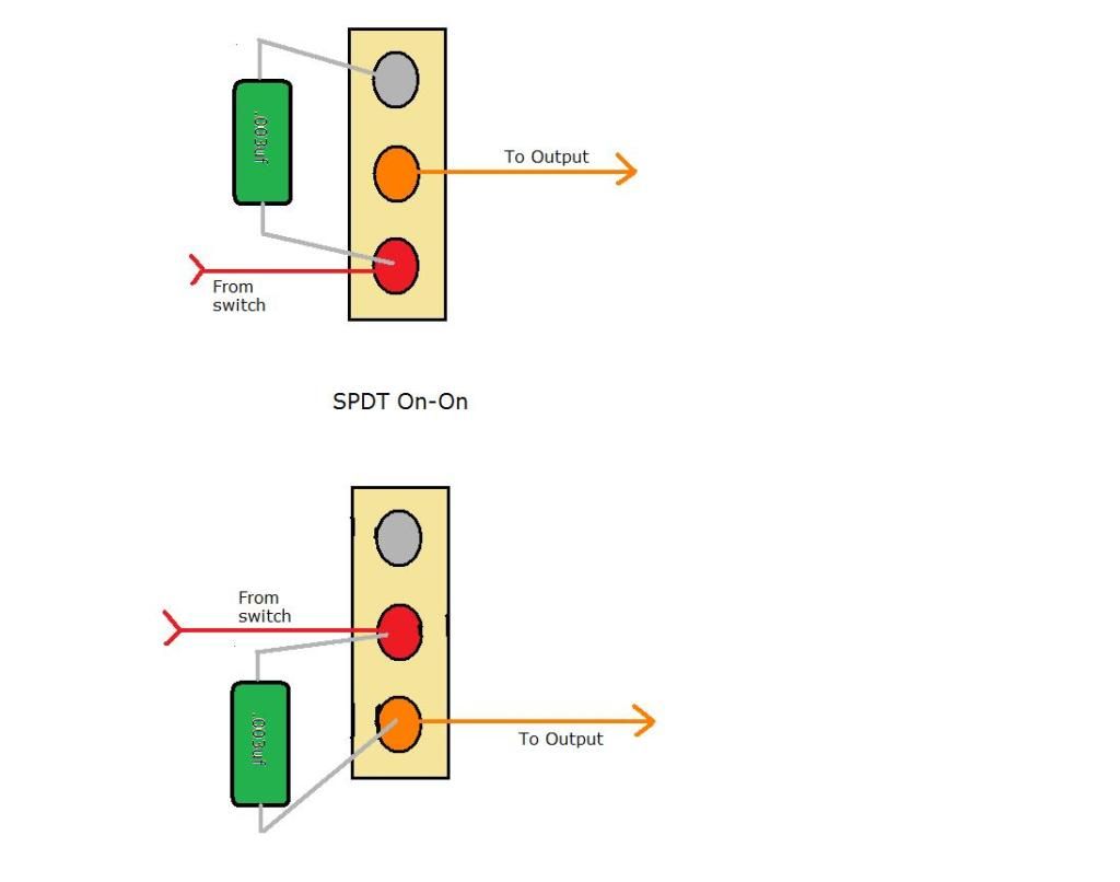 |
|
col
format tables
Posts: 472
Likes: 25
|
Post by col on Jul 24, 2012 22:30:06 GMT -5
Hi guys, You seem to be using DPDT on-on-on switches of 'type D' as seen here: www.1728.org/guitar.htmThese are supposed to be the more unusual variant of 'type C' which is what I am looking for but for the life of me cannot find them. Or should I be opening a new thread? There are some interesting and useful things on that site, but that bit of info is just plain wrong. You can't find 'type C' because to the best of my knowledge, no one makes it. A standard Gibson toggle act like half (one pole) of a 'type C'. But that's as close as you get. Our member wolf, who runs 1728.com and ChrisK had an ongoing debate years ago about wolf's "type C" On-On-On switch. It basically came down to Chris daring wolf to "Find one!". Wolf was unable to do so. So, I think RT is right on that, ain't no such animal. Of course, any switch manufacturer would be happy to make some up for you, provided that you're prepared to order a quantity somewhere north of 10K of the things . . . . Well, maybe they were unavailable at the time, but these type of witches do exist. Or maybe Wolf and others were unable to turn up any results because they used incorrect search terms. These switches are described as SP3T (on-on-on): www.mouser.com/ProductDetail/NKK-Switches/M2024SS1W01-RO/?qs=0RDYWt4CO4crSvrig1fhHQ%3d%3d |
|
|
|
Post by newey on Jul 25, 2012 5:52:01 GMT -5
Col-
That's a single pole switch; the debate was regarding a double pole switch. A SP3T is just like a Gibson-type toggle, as noted above.
As to the link, if you open the .pdf of the product data sheet and look way down the page, the manufacturer notes that they use the same 6-lug frame for the SP switches as they use for the DP switches. So, it looks like a DP switch as it has 6 lugs, but only 3 are internally connected to anything.
They do make a DP3T On-On-On, which uses the same base as the 4-pole switch (i.e., 10 lugs). It is configured like wolf's "type D", not the mysterious "type C".
|
|
|
|
Post by dannyhill on Jul 25, 2012 7:43:27 GMT -5
Ooops too late. I already made up the first.
Thanks guys anyway.
For the record I hear no popping.
D
|
|
|
|
Post by ashcatlt on Jul 25, 2012 10:18:45 GMT -5
Yeah, I mean there isn't any DC voltage across the cap. The only thing you'd need to "worry" about is the instantaneous voltage at switching time. That will basically be some random value, and generally wont be very big.
You might hear some faint clicking - especially in high gain situations. People hear clicking from kill switches when doing that RATM/EVH/Buckethead thing when the instantaneous voltage changes from not zero to zero and back all of a sudden. Even then it's kind of hard to say that's not at least partly switch bounce.
Where you might get into trouble is if the first active stage after the guitar has a bit of leakage through its AC coupling cap or - much worse - is DC coupled on its input.
|
|
col
format tables
Posts: 472
Likes: 25
|
Post by col on Jul 25, 2012 21:35:13 GMT -5
Col- That's a single pole switch; the debate was regarding a double pole switch. A SP3T is just like a Gibson-type toggle, as noted above. As to the link, if you open the .pdf of the product data sheet and look way down the page, the manufacturer notes that they use the same 6-lug frame for the SP switches as they use for the DP switches. So, it looks like a DP switch as it has 6 lugs, but only 3 are internally connected to anything. They do make a DP3T On-On-On, which uses the same base as the 4-pole switch (i.e., 10 lugs). It is configured like wolf's "type D", not the mysterious "type C". Hi newey I know the debate revolves around a 'two pole switch'. However, the switch I linked is described as SP3T because you can wire it up that way. Using your labeling, if 'C' is your common, and is 'E' wired to 'D', your in/outputs, in order, for each throw of the switch, would be: 'A', 'B', & 'F'. Try this link: www.nkkswitches.com/pdf/MtogglesBushing.pdfAbout 40% way down the page, check out the "For 3 Throw (3-on)" section. Switch M2024. The schematic shows pins 3 and 5 externally connected. At the foot of that section, there is a drawing of the switch with pins 3 and 5 wired together, and states, "The SP3T model utilizes a double pole base." It also diagrams a 'double pole' version; or 'four pole, with asymmetric switching', depending upon your point of view. Wolfe was/is correct; the 'type C' switch does exist and is available. Col. |
|
col
format tables
Posts: 472
Likes: 25
|
Post by col on Jul 25, 2012 21:48:34 GMT -5
Ignore my last post - brain fart! I misremembered what I posted only 24 hours ago.  Let me look at this again. Edit: or, indeed, I did misunderstand. |
|