|
|
Post by newey on Mar 3, 2012 10:22:50 GMT -5
We've had some recent discussion about a "mid-cut" control a la Torres Engineering's kit. And Ozboomer has his modified G & L Legacy tone stack in his "modules" post. So, I thought of combining the two ideas into a 3-band passive EQ. I don't have a guitar to put this into just yet, so this is more for discussion. As I drew it, I realized I had more questions than answers. I drew this with just a single pickup for clarity, obviously it could be part of a more complex scheme. It does require a 4-pot setup like an LP-style guitar or similar. And I included a switch to turn the whole mess off, with a choice of direct out (solo setting) or out through the volume control only. 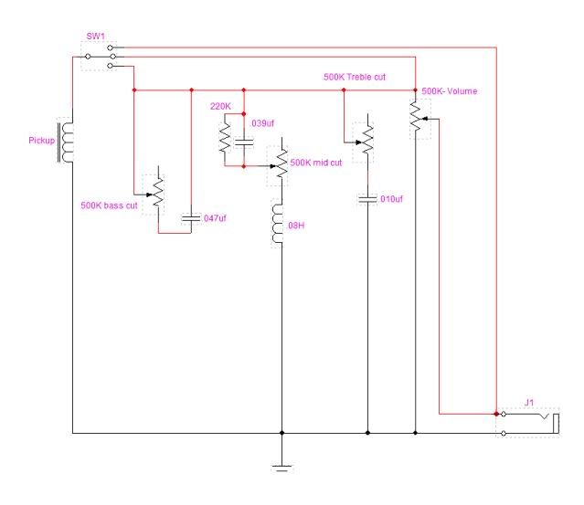 Throwing this up for discussion (and revision, I'm sure). The questions are as follows: - First off, do I have this right? Will it work as intended?
- Will having 4 pots in circuit produce too much mud? Would I be better off moving to 1M pots for some/all of the pots?
- The cap values are just guesses. Would other values work better?
- Same question for the inductor value.
- Finally, this may have to serve as a jumping-off point for me to learn 5spice modelling, which I've not done previously. How would I go about setting that up? Would it need to be three separate graphs, or could I simulate manipulation of more than one pot at a time?
|
|
|
|
Post by ashcatlt on Mar 3, 2012 12:06:00 GMT -5
The bottom two throws of the switch go to the same place. You're looking at it as though the signal will flow from left to right, but all those dots on the third line down are essentially the same place. Gonna take some gathunkin to sort that out. The bass cut control needs to be in series with the signal, while the other two are parallel. Needs at least one more pole on the switch, I think.
The bass cut control won't do anything because it's shorted. Move one of the components (cap or variable resistor) to be in place of that wire which is shorting it out. It should look like a volume pot with treble bleed cap, but with no grounded lug. Of course, I think it was fobits (or was it unclemickey?) who found the bass cut was more pronounced when that third lug was grounded...
I would use 5spice to choose values. It will allow you to sweep up to two component values at a time.
I'd wonder if this is really going to be satisfying. There will be treble loss from all the pots. More generally, passive necessarily means that it is both lossy and sensitive to outside conditions.
Lossy isn't great in a guitar with passive pickups because there ain't much there to begin with. Sure, you can turn up the gain down the road to compensate, but you'll also be turning up the noise in the system.
Sensitive to external factors is rough, too. Different pickups will require different values of just about everything, and then the controls will respond differently depending on what you plug the thing into.
|
|
|
|
Post by newey on Mar 3, 2012 13:07:55 GMT -5
Thanks, Ash. I'll redo this with your points in mind.
So, maybe trying to do too much at once. Back to the drawing board . . .
|
|
|
|
Post by newey on Mar 3, 2012 13:39:00 GMT -5
OK, here's version 2 . . . 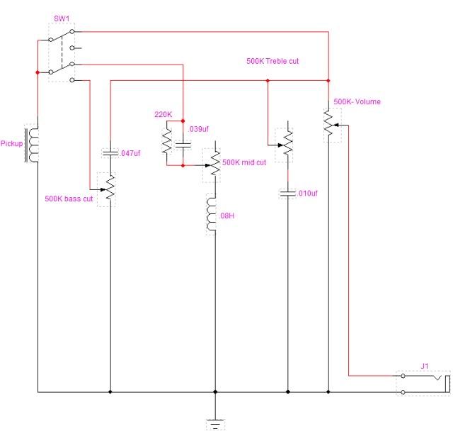 Bass cut is now in series with output. Bass cut and treble cut are now switched in/out of circuit with the mid-cut as the other option. I'm thinking this would lessen the passive losses since it's one less pot in circuit at the same time. It would allow for a mid "gate" effect in one switch position, and a mid "notch" in the other- assuming I've got this right. If it's now OK electrically, I'll try my hand at a 5spice sim. |
|
|
|
Post by reTrEaD on Mar 3, 2012 13:54:51 GMT -5
The bottom two throws of the switch go to the same place. You're looking at it as though the signal will flow from left to right, but all those dots on the third line down are essentially the same place. Gonna take some gathunkin to sort that out. The bass cut control needs to be in series with the signal, while the other two are parallel. Needs at least one more pole on the switch, I think. I agree. Having an additional pole would clean things up a lot. Else your three modes would be: Direct to jack Mid cut, treble cut, volume Bass cut, mid cut treble cut, volume My guess is the center selection was intended to be volume only. The bass cut control won't do anything because it's shorted. Move one of the components (cap or variable resistor) to be in place of that wire which is shorting it out. It should look like a volume pot with treble bleed cap, but with no grounded lug. Of course, I think it was fobits (or was it unclemickey?) who found the bass cut was more pronounced when that third lug was grounded... I don't think the third lug of the pot should be grounded. I think you want the cap and pot in parallel with each other as you described, with the network in series with the signal path. Having the bass cut before the volume control is important. The cap and volume control resistance can work together to form a low-pass filter. But I don't know if it would be better or worse to have the bass cut before the mid cut and treble cut. - First off, do I have this right? Will it work as intended?
Ash noted the problems with the circuit at present. - Will having 4 pots in circuit produce too much mud? Would I be better off moving to 1M pots for some/all of the pots?
You only have 3 pots in parallel with the signal (mid, treble, and volume). The bass cut circuit is in series. I don't think an additional pot in parallel with the two we normally see, will be all that bad. - The cap values are just guesses. Would other values work better?
- Same question for the inductor value.
I think modelling or real world tests will help you more than our opinions. No accounting for taste and all that. But the 0.08H inductor seems much smaller than I would expect. With the 0.039uF capacitor, the circuit would have minimum reactance at 2850Hz. And the bandwidth would be fairly wide. I think you'd be better off with an inductor of at least 1H, maybe as large as 10H. - Finally, this may have to serve as a jumping-off point for me to learn 5spice modelling, which I've not done previously. How would I go about setting that up? Would it need to be three separate graphs, or could I simulate manipulation of more than one pot at a time?
Not 100% certain, but I think the 5spice program John uses can only vary one component at a time. OK, here's version 2 . . . The switching and bass cut still look like a problem to me. |
|
|
|
Post by newey on Mar 3, 2012 14:34:10 GMT -5
RT-
Yeah, you're right, thought I had the switch sorted. V3 coming up . . .
|
|
|
|
Post by newey on Mar 3, 2012 15:08:12 GMT -5
Hmmm, this is getting complex but hopefully the third times the charm . . . I disconnected the bass cut from ground as RT suggested. Perhaps I can model it both ways to see if Fobits (or Unc or whoever was right). I used a dual-gang pot for the volume so as to avoid the switching problem, separating the two halves of the circuit completely. I also re-specified the inductor as 5 Henries, I don't know if that's a value that's available anywhere, but I was just splitting the difference on RT's suggested range, we'll see what the model does once I get the circuit right. Better? 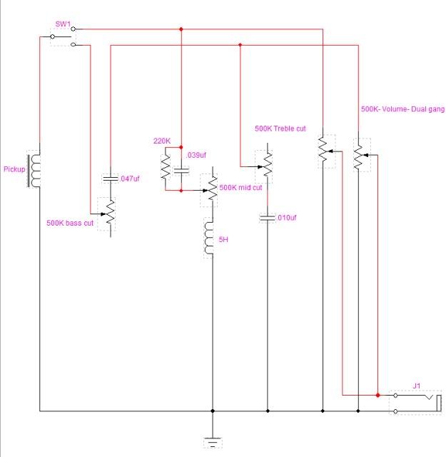 |
|
|
|
Post by JohnH on Mar 3, 2012 15:30:15 GMT -5
Its definitely worth testing it in 5Spice, even if the conclusion is not to rewire your vintage Strat with it just yet. I think the middle and treble control might benefit from being 'no-load' conversions, so you can keep a fairly low value log pot to get some action through the turn, but cut it out completely when not wanted. To build your 5Spice model, I think you would not represent the switch, just the circuit components that you want. Also need to model the pickup impedance and the load impedance. For reference, here is a basic single coil guitar with tone and volume:  To the left, is a signal generator, and some inductance, capacitance and resistance, values shown representing a typical SC pup. More values are references here: Pickup impedance and resonance valuesOn the right, the amp and cable resistance and cable/input capacitance R4 and C3 (maybe 30 to 40pF per foot plus 100pF for the amp) You also need, the ground symbol, and the test point TpV. When you have built that, you analyse, having set up for an AC analysis. Note it does not like hanging ends of wires, so pot wipers need to be connected to an end, if using just two connections. These screen shots show some parameters that need to be filled in, (from another post yesterday). i731.photobucket.com/albums/ww316/JohnDHewitt/GN2/spicescreen1-1.gifi731.photobucket.com/albums/ww316/JohnDHewitt/GN2/spicescreen2-1.gifYou can vary one or two components values as a single sweep, in up to 10 linear increments between specified max and min values. cheers John |
|
|
|
Post by ashcatlt on Mar 3, 2012 15:36:49 GMT -5
Well that's one way of doing it. I think the difference in both cost and space is greater this way than with a DPDT, but...
The bass cut is still wrong. The pot and cap should be parallel to one another, and both in series with the signal. The pot bypasses the cap, or the cap bypasses the pot, or whatever. Exactly like a volume pot with tenor bleed, but no grounded lug. At this point it would almost be easier to draw it for you, but that would mean turning on the computer.
|
|
|
|
Post by reTrEaD on Mar 3, 2012 17:21:27 GMT -5
A little worse, I think. I guess you abandoned the original thought of having 3 different modes. With that in mind, I think the switching in the first version was better than having the wipers in parallel on the third version. That will muck with the taper. And have both volume pots essentially in parallel with each other at the CW end of the rotation. I edited your version 2 to show how the bass cut should look. Unless you come up with other ideas for the switching, that part would be better than version 3. But I didn't update the component values. 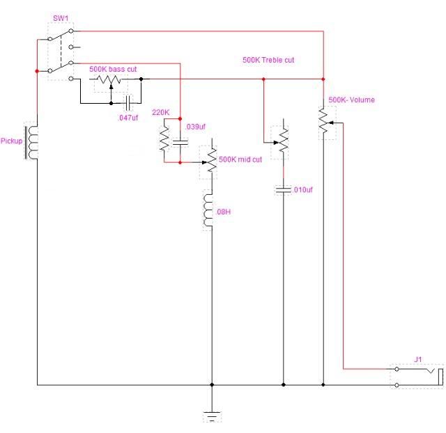 I think the bass cut pot might be better at 1Meg than 500k. Still, it's not likely to give much cut. There may be a better way to configure this, but the arrangement you had in version 3 won't do it. It's more like a volume control. |
|
|
|
Post by newey on Mar 3, 2012 19:01:55 GMT -5
Here's what I came up with for a model of just the bass and treble cuts, eliminating the mid cut: 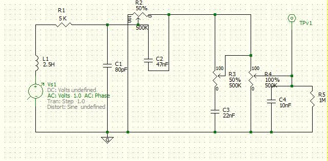 However, I'm doing something wrong on the analysis screen as I just get a single line on the graph even though it's set to sweep the Bass cut control (I did that one alone first, didn't want to try 2 variables at once until I figure out the software.) |
|
|
|
Post by JohnH on Mar 3, 2012 19:11:58 GMT -5
have you ticked the tick box to engage the sweep?
Also, your left bass-cut pot leg would be best not to ground (ie killing all sound at 100%), but connect it to the wiper instead
Also, C4 is too big. should be 0.5nF to represent the cable/amp
J
|
|
|
|
Post by newey on Mar 3, 2012 20:58:40 GMT -5
OK, here's the revised 5spice schematic per JohnH's suggestions: 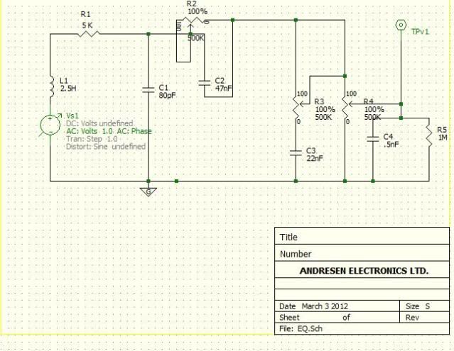 And here's what I'm getting, set to "sweep" both R2 and R3. Still doesn't seem right . . . 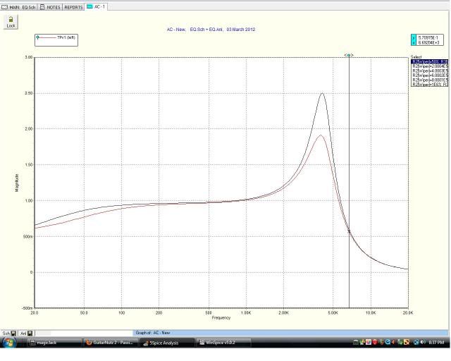 Here's how it's set up for the analysis. This is a cool program but definitely a bit of a learning curve here . . . 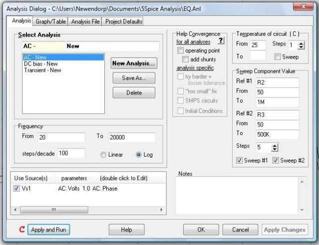 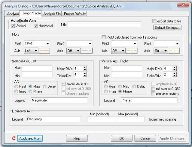 |
|
|
|
Post by JohnH on Mar 3, 2012 21:45:47 GMT -5
I think you are almost OK. I think it is misinterpreting the intent of your sweep commands. When sweeping a pot by representing turning of the knob , do it as from 0, to 100 ie no k or M. It then interprets this as being the % of the turn, with the 0 and 100% settings as indicated on the schematic. For fixed components, you sweep them by values, eg from 1k to 100k etc
|
|
|
|
Post by ashcatlt on Mar 3, 2012 22:35:36 GMT -5
That'll help.
Also, click the "amplitude as db" box on the Graph/table tab. There are times I've used the absolute voltage display, but mostly in active citcuits.
|
|
|
|
Post by newey on Mar 3, 2012 23:03:06 GMT -5
OK, now I seem to be getting results. As a control, I swept R3 alone, which is the treble cut, regular tone control with a 500K pot and a 22nf cap. If I'm reading this right, looks OK, a basic tone control plot: 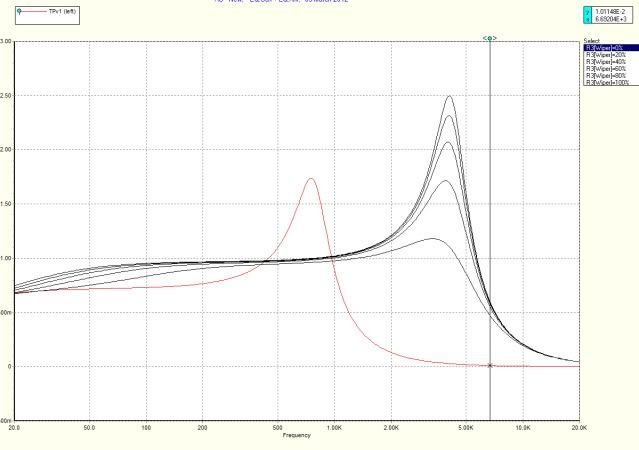 But I tried it with several different cap values; sweeping the bass cut doesn't seem to be doing much of anything at all. Again, assuming I'm reading the graph right, I gather this means minimal variation as the control is turned: First, with a 47nf cap, 1M pot: 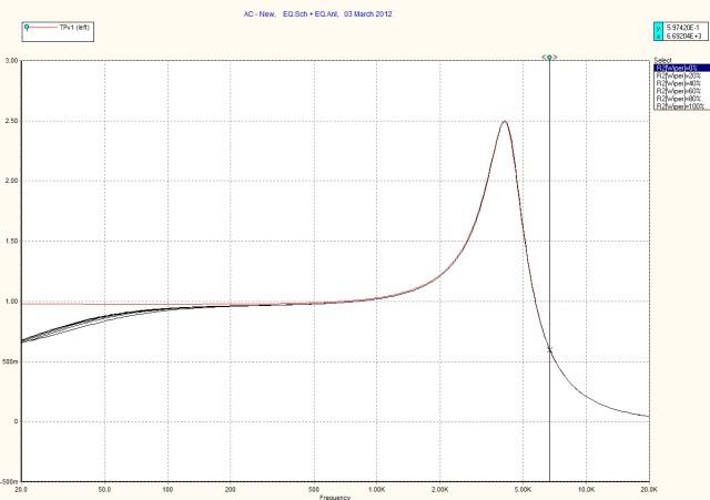 Next, dropping the cap value to 10nf: 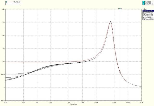 And then, way down to .5nf. Now, I'm getting some variation, but at a cost of a big drop-off in output, again, assuming I'm reading this correctly. 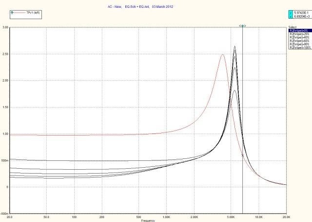 So, first, am I reading this right? If so, I conclude that, with these pickup parameters (std SC values per JohnH), the bass cut isn't worth pursuing. OTOH, ozboomer seemed to find it acceptable on his Strat. So maybe I'm looking at this bass-akwards . . .  |
|
|
|
Post by JohnH on Mar 4, 2012 0:52:40 GMT -5
I reckon the 10nF version might be OK, if you want a bass cut of course. Good idea to set the plots to db instead of voltage ('amplitude in db' box, on the 'graph/table' page
J
|
|
|
|
Post by ashcatlt on Mar 4, 2012 1:16:23 GMT -5
Keep in mind, too that these are linear pots being modeled. Or rather, the % shown is % of total resistance between the 0 lug and the wiper. A logarithmic pot will spend a much greater proportion of its rotation in that "big drop" region between those first couple steps.
What does 4.7 nf do? The 10nf is -6db right around 50Hz. Half that (fudged to a standard value) should move it up an octave, just below the fundamental of the low A.
Also, why not try grounding that other lug, just see what it does?
|
|
|
|
Post by reTrEaD on Mar 4, 2012 6:40:18 GMT -5
Also, why not try grounding that other lug, just see what it does? Ash, my first reaction to this was don't do it, because it would shunt all the signal when the control was at minimum. But after some thought, this is moving in the right direction. Instead of grounding it directly, I think a fixed resistor between the CCW lug and ground would be good. One of the challenges of the simple bass cut is that it puts the cap in series with the signal, but it depends on other resistances in the circuit to form a high pass filter. So having a resistor that's smaller to serve that function (when needed) would allow us more cut. I think having the treble cut before the bass cut might result in less interaction between the two controls. I butchered one of newey's drawings to show what I think might be a good starting point. 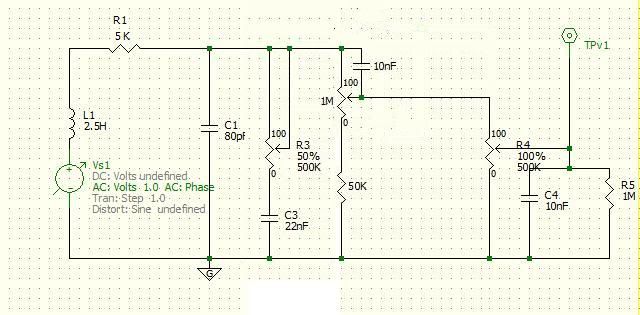 Do you think it might work? |
|
|
|
Post by newey on Mar 4, 2012 9:52:49 GMT -5
Good point, Ash, I hadn't considered the taper. As I looked at the graphs, it seemed like rotating the pot wasn't doing anything. I'll try RT's version, and Ash's suggestion, in a bit. Meanwhile, I tested the mid-cut. First, I tried it with a 10H inductor, as RT had suggested might be the value needed. The cap was originally set at 47nf and the resistor at 100K: 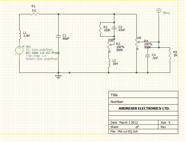 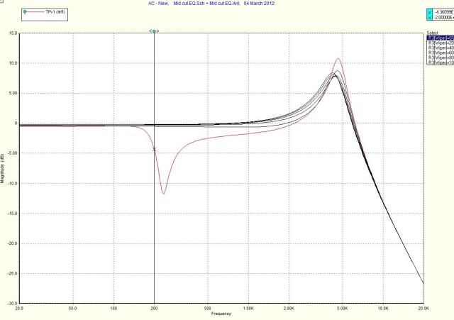 Note that the cut here is about 200Hz, not exactly midrange! And, once again, all the action seems to be between 20% and 0% on the pot, but recalling what Ash noted, maybe it would be OK with a log taper pot. Changing the resistor value to 220K and the cap to 60nf (somewhere those values were noted as what Torres uses for their unit) deepens the cut quite a bit, but we're still at 200Hz. And still all between 0%-20%. 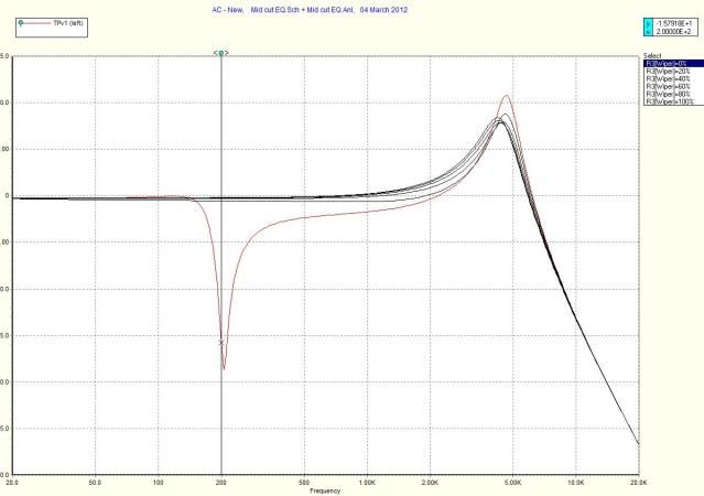 So, altering the inductor value to 1H moves the frequency cut into the midrange. Cap and resistor still at 60nf and 220K, respectively: 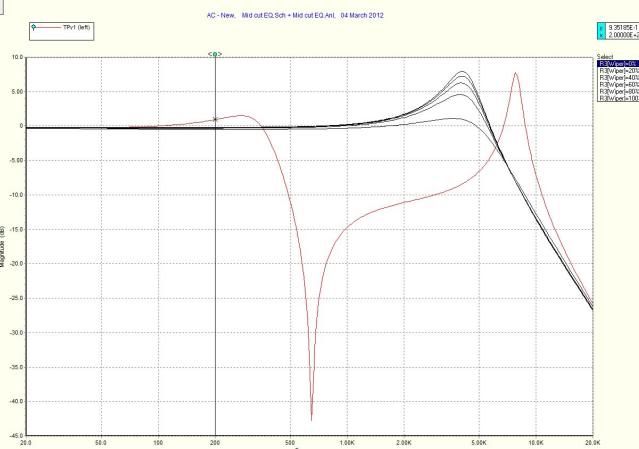 It's still in the lower end of the midrange, so I'm thinking that about .75H might be better. |
|
|
|
Post by newey on Mar 4, 2012 10:01:40 GMT -5
Actually, .5H gets us reasonably close to 1KHz: 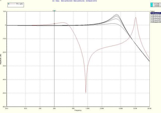 But also note that we seem to be getting a bit of a "bump" at about 350Hz, looks to be about 2dB, and an even bigger bump up between 4K- 10K. What's that all about? |
|
|
|
Post by newey on Mar 4, 2012 10:12:06 GMT -5
OK, now we're back to the bass cut. The cap was sent to 4.7nf per Ash's suggestion: 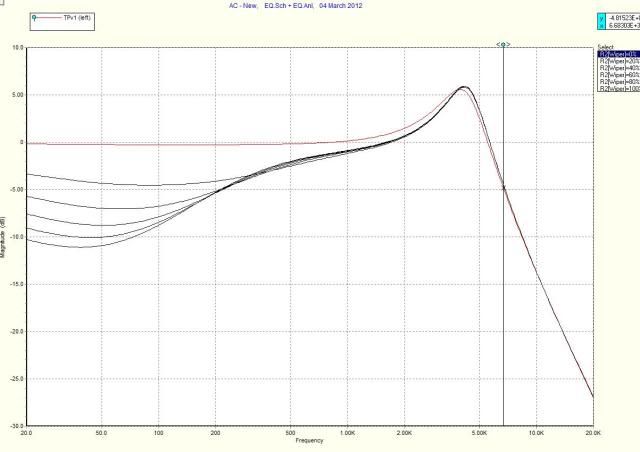 Now I seem to be getting more variation from the pot roll-off, but we're still down around 50Hz. The cut is still occurring towards 100Hz, though. EDIT: The difference in pot roll-off is probably attributable to setting the scale to dB, as JohnH suggested. |
|
|
|
Post by newey on Mar 4, 2012 10:35:38 GMT -5
OK, I redrew it as per RT's diagram. I'm not clear on why the value of C4 was changed to 10nf from .5nf. 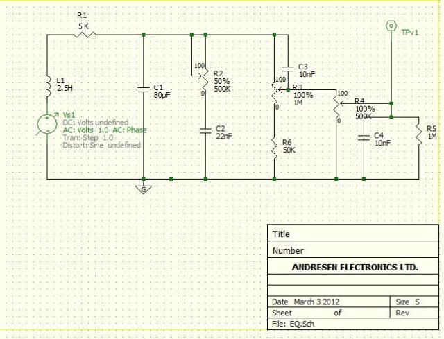 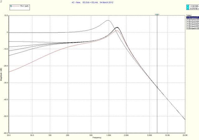 Hmmm. Not sure what to think of this one . . . |
|
|
|
Post by newey on Mar 4, 2012 10:44:37 GMT -5
Here's RT's version, but with C4 set back to the original value of .5nf. As I understand it, C4 models the cable capacitance, so this presumably represents using a shorter cable: 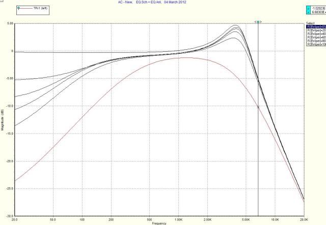 |
|
|
|
Post by reTrEaD on Mar 4, 2012 13:47:55 GMT -5
OK, I redrew it as per RT's diagram. I'm not clear on why the value of C4 was changed to 10nf from .5nf. Sorry, Newey. I grabbed the wrong diagram to start with. It came from post 10. I should have used the one from post 12. I think the bass cut with 50k to ground is too effective. Imho, the most you'd want is about 12~15 dB. Try increasing the value of R6 to 100k or perhaps even more. MID CUT: I don't like what I'm seeing in the mid cut for the smaller inductors. 40~50 dB is WAY more cut than you would ever want. Instead of making the inductor smaller to shift the frequency upward, you could make the cap smaller. Or you might put a fixed resistor in series with R3 to limit the minimum resistance. You should try varying the value of R2 without changing other values, to determine how it affects things. I'm guessing lower values might make the "notch" broader and higher values might make it narrower. |
|
|
|
Post by JohnH on Mar 4, 2012 14:38:59 GMT -5
With these mid-cut ideas, any time that there is a direct path from hot to ground via a cap and inductor in series (and no resistance), there will be a very deep notch at the frequency where impedances of th ecap and inductor match. In fact it will be infinitely deep with theoretical components. This is because a cap and inductor in series have zero impedance at this frequency. So to limit the depth of the notch, either the pot is not fully turned down, or there is a fixed resistor in series with it all, within the mid v=cut circuit between hot and ground. also, in the GuitarFreak spreadshett (reference section), version 2.2 will do pot, cap and inductor, which can make a mid control: i731.photobucket.com/albums/ww316/JohnDHewitt/GN2/Guitarfreak22.gifIts handy to be able to slide the controls and quickly see the results, in real time, instead of having to do a run then look at plots. cheers John |
|
|
|
Post by newey on Mar 4, 2012 15:05:30 GMT -5
Yeah, after I posted those mid-cut analyses, I began to wonder how to widen the notch, so I'll experiment some more.
John, when I last tried the Guitarfreak spreadsheet, I couldn't get it to run in Vista. But now, I can try it on my netbook running Windows 7, so I'll fire that up and give it a try.
|
|
|
|
Post by roadtonever on Mar 4, 2012 16:41:00 GMT -5
Try it in LibreOffice, works for me in Windows 7, should work on Vista too. |
|
|
|
Post by newey on Mar 4, 2012 19:00:26 GMT -5
OK, on the Mid cut, adding a resistor as JohnH suggested gets rid of the spike, and playing with the other values a bit gets a nice mid scoop from about 750Hz to about 4KHz. Still, all the action is between 20% and 0% on the pot. I played with all the values and these seemed to be the best compromises. Of course, I'm still open to suggestion. Here's the revised circuit, adding the fixed resistor to ground after the inductor: 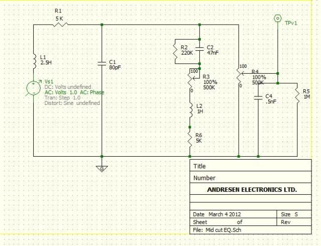 And here's the graph: 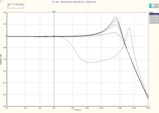 |
|
|
|
Post by JohnH on Mar 5, 2012 3:35:29 GMT -5
If all the action is 0 to 20%, then how aboout a 100k pot, with a 'no-load' cut in the track? maybe a 100k log.
|
|


