|
|
Post by flateric on Mar 10, 2012 11:22:52 GMT -5
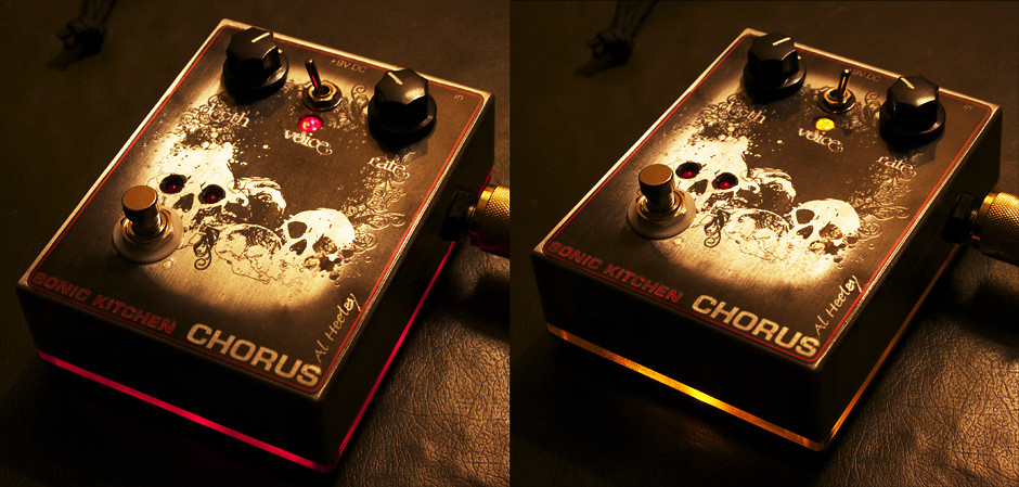
This is another small clone chorus pedal build using the schematics from Tonepad dot com - a clone of the classic analog Electroharmonix Chorus with a couple of mods thrown in. Thought it might inspire some more people to have a go with a step-by-step walkthrough. 1) PCB etched and drilled after UV-exposure & development. I start by soldering the IC holders then work my way through the resistors.  2) All resistors in place plus mini trim pot for fine tuning the chorus sweep  3) Next I move on to the capacitors, small ceramic caps first followed by the larger electrolytic ones  4) Once the components are all soldered in place I fit the IC's and transistors then move to the board wiring. A couple of mods from the original circuit seen here - a) Orange lead on left takes current from leg 1 of the op amp chip, feeding to a rate indicator LED, so rather than just an off/on indicator LED, this pulses in time with the settings of the rate control to give a visual indication of chorus speed setting. b) blue/white striped wires on right taken from the pcb to replace the stock 150pF cap; this determines the overall delay depth. The wires will go off to a mini toggle switch allowing choice between 100pF and approx 350pF cap to choose a light or deep voicing for the chorus.  5) Enclosure innards, drilled and fitted with 3PDT footswitch, jack plugs, rate and speed pots, LED indicators plus voicing switch.  6) Here's the outer - graphics printed onto self-adhesive clear inkjet film (eg: makes a good job with the polished aluminium box showing through. The rate indicator LEDs are a couple of red surface mount LED's set intot eh eye sockets of the skull graphics.  Next step is to wire the board into the enclosure after a quick test run to ensure the circuit is all functional. |
|
|
|
Post by JohnH on Mar 10, 2012 15:50:02 GMT -5
Very good and helpful +1. I'd be interested in more of your observations about making the pcb. What sort of tools do you use, and how tricky is it to get your drilling in the right place. Are you using a drill press?
cheers
John
|
|
|
|
Post by sumgai on Mar 10, 2012 17:40:37 GMT -5
♭eric, I see in the last photo that you've been dropping globs of hot solder onto your wife's cutting mat. That's gonna cost ya.......  ;D sumgai |
|
|
|
Post by flateric on Mar 10, 2012 18:56:50 GMT -5
I am truly sorry about the cutting mat. Honest. That's washing up duty for a week and kid taxi service penance. With all true art there has to be sacrifices. I'm sure you'll help her understand.
JohnH pcb: I used to scrape through with resistant transfers and hand drawn pen traces before Ferrous chloride etching, but these circuits are too complex to work well on this, so it's off to a good friend down the road who happens to be an electronics genius with a home-made uv-box. The graphics are printed out onto clear ink-ket transparencies then given 4 mins UV exposure against Farnell UV-photoresist copper boards, before developing in sodium hydroxide and etching in FeCl. Holes are drilled using my reading glasses and a steady hand with a dremel, i don't bother with a drill press. if the etch works well, there's already a starting hole to attack. The biggest problem is balancing the exposure time and the developer time to get best results.
|
|
|
|
Post by flateric on Mar 13, 2012 15:19:15 GMT -5
pedal finished, wired up and ready to go  |
|
|
|
Post by flateric on Mar 19, 2012 18:13:53 GMT -5
Final pic, finished unit with bicolour LED's lighting the base plate according to voice depth switch setting, and the red rate LED's pulsing in the skull eye sockets. Must get round to recording a sound clip.  |
|
|
|
Post by newey on Mar 19, 2012 22:39:00 GMT -5
eric-
The skull with the LEDs in the eye sockets is wicked cool! If that's an original idea, better trademark it before the Big Boys copy it from you! +1 for another beauty.
|
|
|
|
Post by flateric on May 10, 2012 5:31:31 GMT -5
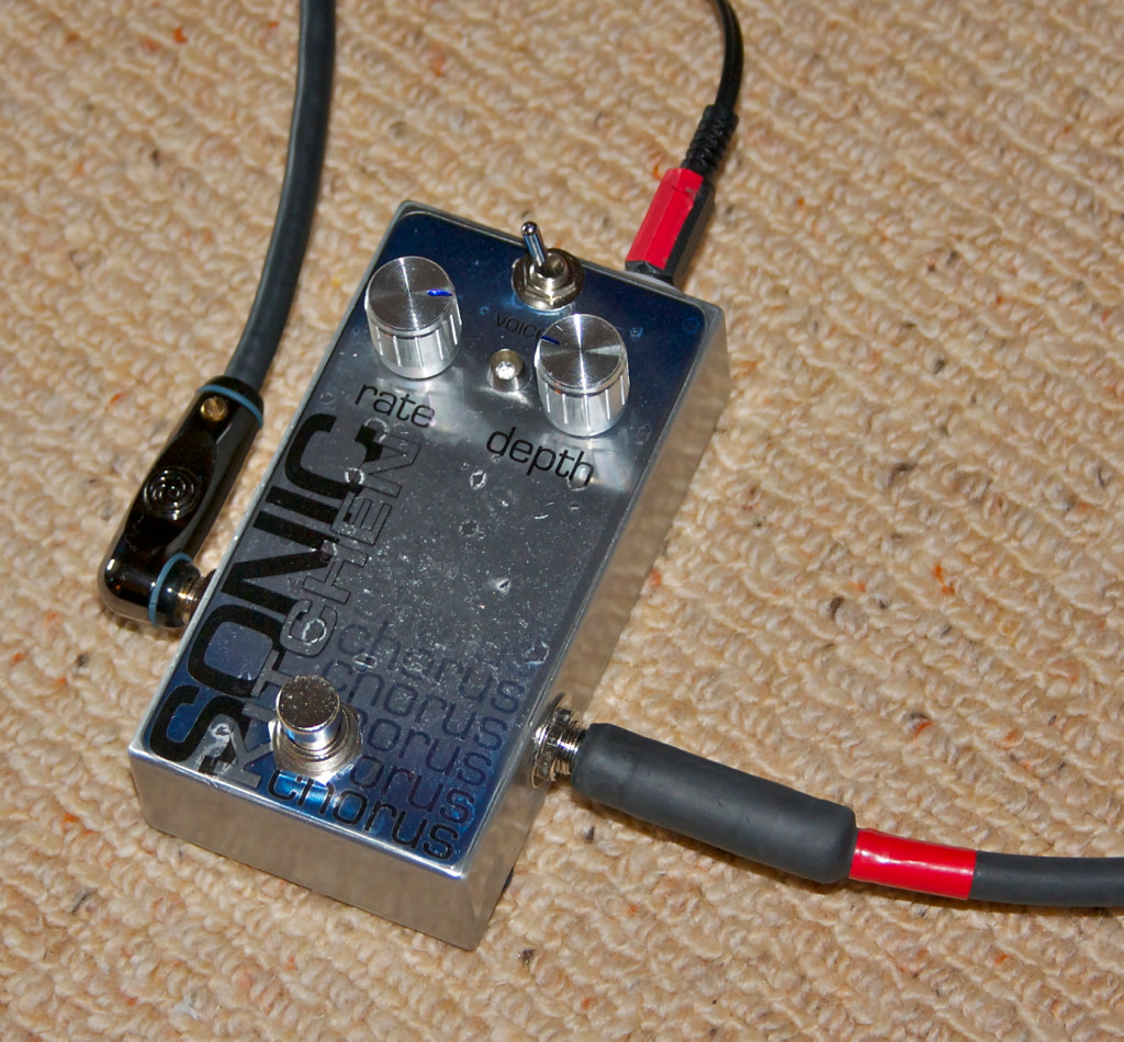
Here's another chorus build in the smaller enclosure, tight fit to get all this in. Same mods as before - 2-depth voice switch and the heartbeat LED rate mod.  |
|
|
|
Post by andy on May 14, 2012 18:23:17 GMT -5
bicolour LED's lighting the base plate according to voice depth switch setting, and the red rate LED's pulsing Really?! That is almost too cool to be for real! Those base plates look great. |
|