|
|
Post by yakkmeister on May 3, 2012 11:11:00 GMT -5
Hey Nuts! I posted this before but it seems to have gotten lost in among all these interconnected tubes ... Building a champ clone and putting a cap-bypass on the bypass cap (it's parallel to the bias resistor off pin 3 on the 12AX7). 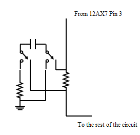 There's the idea I have in mind. What I need to know is: Will the cap discharge in this config? What would be a good resistor value? |
|
|
|
Post by sumgai on May 3, 2012 19:25:47 GMT -5
yakker, You do realize that you aren't so much as bypassing the cap as you are simply removing it from the circuit, right?  And there is no "rest of the circuit", the cap/resistor combo from Pin 3 is intended to go to ground. (Although you did mention "clone", which may change that picture somewhat, but not enough to make a difference. If it does, then it's no longer a Champ-clone.) The deal here is, the resistor sets the negative voltage point that the cathode will see, compared to the anode (aka the plate, or Pin 1 in this case). But when the resistor is alone, it's passing both AC and DC in the circuit, and that's not the best way to get gain/tone/both. Using a cap in parallel gives us a very easy way for AC to get to ground (the cap's nominal value is usually 15 to 25µf), yet not disturb the DC level set by the resistor. Now we can get some serious gain from the amp stage. In your scenario, you've place the cap in parallel with an external resistor that has no other connection with the overall circuit - the only time it comes into play is when the cap is disconnected from the cathode resistor. IOW, that second resistor is doing nothing but burning up your wallet! (All 50¢ of it.) You can achieve the same effect with an SPST switch that disconnects one cap lead from the circuit. Strictly speaking, what you've done isn't bypassing the cap. Bypassing a component is defined as shunting around it (in British parlance), or shorting it out (in American slang). In the case at hand, shorting the cap would also short the resistor, and that means that the cathode would be at ground potential - not the desired results! Whereas, the name "bypass cap" means pretty much just that - it means that the cap is bypassing the AC component of the voltage(s) straight to ground, effectively shorting the resistor insofar as AC is concerned. The name is apropriate for the circumstances. So, given the above explanations, do you still want to remove the bypass cap? And if so, why? My suggestion might be to change it somewhat in value, and/or change the resistor a bit, too. This can be done with some switching, should you wish to experiment, looking for best tone, gain, etc. (At this point in the circuit, you are monkeying around with low voltages, both AC and DC, something on the order of 10 volts or less.) Questions?  HTH sumgai |
|
|
|
Post by yakkmeister on May 3, 2012 20:34:29 GMT -5
Yessum. I suspected as much. It's not clearly indicated on the circuit diagram I have though ... which I found annoying ... The company I got the kit off is run by a guy who makes amps for Australian country music players - Troy Cassar Daley and the like - Keith Urban has an appointment to get an amp built for him. This bloke, Mal, has the aim of making clean amps that do not distort. I had the privilege of playing about 6 amps he'd designed and built - one of which actually belonged to Troy ... but we won't tell him that ... They all have this beautiful chime and crystal clean sound. He mentioned that by sacrificing the gain over the 1st triode the amp will clean up and have a similar character to his. Another project (down the line) will have multiple caps but it will also be a different and slightly more powerful design. Do I want to still do this? Yes. It should be trivial to re-wire the switch to include a different cap value instead of just taking the bypass cap out of circuit... I hope?  |
|
|
|
Post by reTrEaD on May 4, 2012 1:52:17 GMT -5
He mentioned that by sacrificing the gain over the 1st triode the amp will clean up and have a similar character to his. Yes, this will definitely decrease the gain. It should be trivial to re-wire the switch to include a different cap value instead of just taking the bypass cap out of circuit... I hope?  I wouldn't. A smaller cap will still be effective at keeping the gain high at higher frequencies. But at lower frequencies the gain will drop off. You want this to occur at a low enough frequency that you won't notice a loss of bottom end on your guitar. If you want more choices in gain, use two resistors in series for the cathode resistor. Connect one end of the cap to ground. The switch connects the other end to the cathode, or the link between the two resistors, or not connected. |
|
|
|
Post by yakkmeister on May 4, 2012 2:46:03 GMT -5
I thought we were saying this was a bad idea? The resistor I put over the cap when switched out of circuit was to speed up it's discharge ... Though I don't think that's even useful - meaning a SPST would do the job more efficiently. The cap is a 25/25. Also; Sumgai - It began as a clone - it's less clone now and more 'derivative'  I had to modify a few things to get the features I was looking for ... ^_^ |
|
|
|
Post by newey on May 4, 2012 4:49:02 GMT -5
He means the other resistor, the one from pin 3.
|
|
|
|
Post by yakkmeister on May 4, 2012 5:10:05 GMT -5
He means the other resistor, the one from pin 3. I meant the other-other one, the one that's only over the cap when it's out of circuit. What I have proposed should achieve the same result but with only 2 options: cap bypasses bias resistor: high gain, dirty cap out of circuit: low gain, clean I read RT's concept as being: cap bypasses both resistors: high gain, dirty cap bypasses one bias resistor: less gain, I think. cap out of circuit: low gain, clean. Thus I ask if this isn't what was just pointed out as a bad thing. I should have used a new line for the resistor-over-the-cap statement as it's a bit misleading where it is; sorry! |
|
|
|
Post by sumgai on May 4, 2012 14:34:05 GMT -5
yakky, It's generally considered "bad form" to omit entirely the cathode's bias resistor - after all, that's intended to set the DC voltage point, which works in conjunction with the grid's bias voltage to make the tube operate the way we want (in a linear fashion). One shouldn't rely solely on a capacitor for this important job. Experiment with caution, although I'm not so much concerned with tube damage as I am tone.
Ken Fischer was the foremost known such experimenter (he certainly was not trained in any classical fashion, and made no bones about it), but he did gain his reputation the hard way - one amp at a time. Ken made his 15 Warhols by monkeying around with, you guessed it, the cathode components in the pre-amp stages. Sadly, I've just come back from an extended Googling of the Innerwebs, and there are no longer any extant pages detailing Ken Fischer's Trainwreck mods. This is a travesty, to my way of thinking. Not even in The Wayback Machine, boo-hoo-hoo.  So now I must turn to the dead-tree reference..... I suggest that you get your hands on a copy of Gerald Weber's Desktop Reference of Hip Vintage Guitar Amps (link goes to Google results page), wherein you'll find a lot of notes from Fischer's Trainwreck mods. In my copy, it starts on page 171, and runs for about 30 pages. I think you'll get more than you bargained for, if you can stick with it! ;D (Note: In further investigation, I've learned that you can now order this book in eBook form. Also, you can try for a used copy at many places, both brick-and-mortar and on-line.) HTH sumgai |
|
|
|
Post by reTrEaD on May 4, 2012 17:09:10 GMT -5
What I have proposed should achieve the same result but with only 2 options: cap bypasses bias resistor: high gain, dirty cap out of circuit: low gain, clean I read RT's concept as being: cap bypasses both resistors: high gain, dirty cap bypasses one bias resistor: less gain, I think. cap out of circuit: low gain, clean. Thus I ask if this isn't what was just pointed out as a bad thing. I should have used a new line for the resistor-over-the-cap statement as it's a bit misleading where it is; sorry! It looks like you understood the first part but got confused about what I meant on the second part. A drawing should help. Generic values shown, but you should have no problem tailoring them to fit your circumstance. 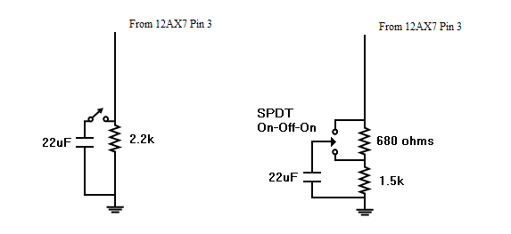  |
|
|
|
Post by yakkmeister on May 4, 2012 20:18:33 GMT -5
Sumgai: Thanks for the reply mate - I would like to point out that I am not trying to remove the bias resistor, only the bypass cap. Sorry for the confusion there. RT: That first drawing is pretty much what I initially expected to do but not anything close to that elegant. Also, I was told that the bypass cap would need a resistor over it so it discharges... I am happy to only have the 2 modes at this point - future projects can benefit from more experimentation as this is the fist one and I'm keeping it as simple as I am able (while still setting it up to be as useful as possible). So, I am happy to build with a switch wired like the first drawing. edit: RT - That's pretty much exactly what I thought you were saying in terms of layout. At what point did you think I missed the point? I am anxious to learn as much from this build as humanly possible ...  |
|
|
|
Post by reTrEaD on May 5, 2012 0:40:59 GMT -5
RT: That first drawing is pretty much what I initially expected to do but not anything close to that elegant. Also, I was told that the bypass cap would need a resistor over it so it discharges... There are some cases where you would want a capacitor to discharge when disconnected, but this isn't one of them. Keeping this capacitor charged will prevent a thump when the switch closes. You could add a 1Meg resistor across the switch lugs to insure the cap stays charged. At what point did you think I missed the point? When you said "I thought we were saying this was a bad idea?" |
|
|
|
Post by sumgai on May 5, 2012 2:43:43 GMT -5
rT, Sadly, I have to admit that I pictured (in what passes for my mind) a different circuit than your drawing.  Good thing we can all use pictures, because words can be misconstrued so easily....  sumgai |
|
|
|
Post by yakkmeister on May 5, 2012 5:16:51 GMT -5
I was told the opposite ... unless I misunderstood. Happy to trust you on this. Sounds good - which lugs? Sumgai, that actually clears up everything! I am going to try and get a copy of that book you mentioned too - looks good! I'll add it to my library  |
|
|
|
Post by reTrEaD on May 5, 2012 10:29:05 GMT -5
Good thing we can all use pictures, because words can be misconstrued so easily....  Happens all the time. Misunderstandings hinge on ambiguous words or phases. It can be difficult, almost an art, to assemble a sentence that is universally understood. There is also an art to saying one thing that will likely be misinterpreted as meaning the opposite. We call masters of that art "Politicians". I was told the opposite ... unless I misunderstood. Happy to trust you on this. Possible you understood correctly but were given bad information. IF we were dealing with a capacitor that was connected to a purely AC signal (like a guitar pickup), it would be beneficial to discharge the cap. We can't know what part of the cycle the signal will be at when we disconnect it. And we can't know what part of the cycle we'll be at when we reconnect it. Worst case scenario would be if the signal was at its highest positive voltage when we disconnected it and at its highest negative voltage when we reconnected it. At the instant we reconnect it, the cap is trying to slam the signal in the positive direction. * click* The same would happen in reverse if the signal was negative when we disconnected the cap and positive when we reconnected it. Discharging the cap doesn't cure the problem, but it makes it less severe. If the signal is at its largest negative voltage when we reconnect it, the cap will try to slam the signal toward zero. We still get a click, but it's smaller. Now let's look at your application.The DC voltage on the cathode is dependent on the size of the resistor and the current through it. Expect a something on the order a 1 mA and a 2.2k resistor. So about +2v DC. Without a bypass capacitor, the change in cathode voltage will almost follow the change in voltage at the grid (input). If the guitar signal is at +0.1v at a particular moment in time, the voltage at the cathode will increase by almost that much. So about +2.1v. If the guitar signal is at -0.1v the cathode will be at about +1.9v. Now imagine what would happen if we reconnected a cap that was discharged in either of these conditions. The cap will try to slam the voltage at the cap toward zero. Whether the voltage at the cathode is +2.1 or at +1.9, the result is pretty much the same. * bam* So keeping the cap charged to about +2v is MUCH better than discharging it. Sounds good - which lugs? For the circuit on the left the switch is a SPST, there are only two lugs. So that's a no-brainer. For the circuit on the right, connect it between the pole and the upper throw. |
|
|
|
Post by yakkmeister on May 5, 2012 17:58:13 GMT -5
Sounds good - I think I have a handle on that now.
Thanks mate!
Off to work then, when I get home, sort out a star-ground scheme for this amp...
|
|
|
|
Post by sumgai on May 5, 2012 20:40:44 GMT -5
Off to work then, when I get home, sort out a star-ground scheme for this amp... To what purpose?   |
|
|
|
Post by yakkmeister on May 5, 2012 21:49:21 GMT -5
Off to work then, when I get home, sort out a star-ground scheme for this amp... To what purpose?   Best Practice and it's too late to do a buss-style ground. Give the thing the best chance at being the best amp it can be. Cos this makes sense: www.aikenamps.com/StarGround.html |
|
|
|
Post by sumgai on May 6, 2012 4:51:47 GMT -5
yakky, You do know that I have "issues" with several so-called amp gurus found in various corners of the web, right? Aiken is one of them, and this is a prime example of why. Let me cut to the chase here: if this was such a good idea, don't you think that Leo, et al. would've thought to execute on it? In fact, Leo did use "best practices", but not to keep so-called "high output stage ground currents" from "modulating the pre-amp stages". [glow=red,2,300]HOLY JEEBUS!  [/glow] Just as an exercise, can you spot the flaws in his argument? I'll keep you on track, don't worry about that.  sumgai |
|
|
|
Post by yakkmeister on May 6, 2012 5:26:16 GMT -5
I didn't know that ...
Sounds like a good idea!
I'll get cracking on it tomorrow - 9 hour day = little energy left.
|
|
|
|
Post by reTrEaD on May 6, 2012 11:06:42 GMT -5
You do know that I have "issues" with several so-called amp gurus found in various corners of the web, right? Aiken is one of them, and this is a prime example of why. I really don't understand why you would lump Randall in with the noise found on the interwebs. I've read his shiz and completely agree with 99% of his opinions. Let me cut to the chase here: if this was such a good idea, don't you think that Leo, et al. would've thought to execute on it? I have no doubt Leo would have thought about using it. But being half bean-counter / half engineer, he wouldn't put an extra nickel in something unless he had to. Good enough was good enough for Leo. Unless it was basically free, something would have to make a HUGE difference, else he would just keep it simple and cheap. In fact, Leo did use "best practices", but not to keep so-called "high output stage ground currents" from "modulating the pre-amp stages". [glow=red,2,300]HOLY JEEBUS!  [/glow] Just as an exercise, can you spot the flaws in his argument? I'll keep you on track, don't worry about that.  The flaw in his argument is that although this is a REAL issue, it's minor in regards to a (low-gain) amp. Depending on the number of stages, this will lead to a small amount of either negative or positive feedback. Positive feedback makes an amp less stable. This is something you DON'T want in a hi-fi amp. But in the case of a guitar amp, it might actually add more "character", when overdriven. Or it might sound a little worse. Depends on your tastes and how lucky you get with your grounding scheme. Guitar amp manufacturers have traditionally ignored several "best practices" techniques. DC power to the heaters for preamp tubes? Nope. Too expensive. Elevating the AC heater supply to a positive DC potential? Nope. Even thought this is quite cheap to accomplish and moderately effective in reducing hum in the early preamp stages, you rarely see this in a guitar amp. It doesn't take a rocket scientist to figure out why. It won't make all that much difference if the rest of the design and layout are prone to hum and noise. And in most guitar amps, they are. When it comes to "best practices" guitar amps are generally the poster children for what NOT to do. With a modest budget and a LOT of time, and experienced builder could reduce the noise floor by at least 10dB, maybe even 20. But unless you really know what you're doing, you might make things even worse. teal deer: Experiment to your heart's content on an amp you don't really care about. But don't f with your favorite amp until you've had sufficient real-world experience. |
|
|
|
Post by yakkmeister on May 6, 2012 22:23:19 GMT -5
Can one tell from the schematic or layout which way this would go?
Does star-grounding prevent feedback or promote positive over negative? Vice-versa?
I have a negative feedback loop and associated break (open? Turning-off-ing?) switch in the amp as well. I like the idea of providing the 'tighter' and 'looser' character in the one amp.
This was my understanding. What I want to achieve is the least interference from poor ground so i can gain a little clarity, even while overdriven.
Is there really a problem with using a distributed star ground? Seems like it's a good idea. Also - I can, very simply, continue to wire with the usual fender-style grounding.
|
|
|
|
Post by reTrEaD on May 7, 2012 12:25:02 GMT -5
Can one tell from the schematic or layout which way this would go? A schematic is useless for determining current induced voltage drops. They don't accurately show all the individual ground paths in the actual circuit. With an accurate layout diagram you could make some predictions, but you would have to do some very tedious calculations. Does star-grounding prevent feedback or promote positive over negative? Vice-versa? The point of star grounding is to use a singular reference point for all branch circuits. It eliminates the possibility of current on one branch from causing a change in voltage at the reference point of another branch. So eliminates feedback of any kind, via the ground circuit. This was my understanding. What I want to achieve is the least interference from poor ground so i can gain a little clarity, even while overdriven. I hope we're not talking about your favorite amp. See my previous post for recommendations. Is there really a problem with using a distributed star ground? Seems like it's a good idea. Problem? There definitely could be. It all depends on what you do at the subordinate ground(s). Since all branches that share a subordinate ground will see the same voltage drop, relative to "true" ground, the cumulative currents through the wire that connects subordinate to true will generate a voltage drop between those two points. Since a wire is a very small resistor, the voltage drop will be miniscule, unless the current is high. Do something stupid, like running heater current through a subordinate ground an you'll be in a world of hurt. Subordinate grounds are certainly more convenient than running each and every branch path through separate wires, back to a singular ground. But we have to be mindful of the currents that will share a common path to true ground. |
|
|
|
Post by yakkmeister on May 8, 2012 8:35:37 GMT -5
Yeah, I figured as much ...
Sounds like exactly what I want it to do.
I thought I mentioned in my first post that this is a from-scratch build?
Well, based on a kit. Plenty of differences though.
I've the switch I was asking about (to take the bypass cap out of circuit), a negative feedback loop and associated switch in a 2x8 combo and a very groovy cabinet (in the process of being built by my own self). So it's champ-based, a simple little first build.
All the literature I have been reading on the subject mentions those same points. Definitely one to plan with care.
|
|
|
|
Post by reTrEaD on May 8, 2012 9:40:31 GMT -5
I thought I mentioned in my first post that this is a from-scratch build? Well, based on a kit. Plenty of differences though. I've the switch I was asking about (to take the bypass cap out of circuit), a negative feedback loop and associated switch in a 2x8 combo and a very groovy cabinet (in the process of being built by my own self). So it's champ-based, a simple little first build So you did. For some reason that part slipped right by me. My bad. Do you have an electronic version of the layout and/or schematic? |
|
|
|
Post by yakkmeister on May 9, 2012 3:23:24 GMT -5
I don't, but I can find one. I have been using the one that came with the kit (the wiring diagram that also came with the kit is super hard to follow ... I think it was printed on a dot-matrix printer in the middle of a hdd failure whilst in an electrical storm off the Cape of Good Hope ...
|
|
|
|
Post by yakkmeister on May 10, 2012 3:01:59 GMT -5
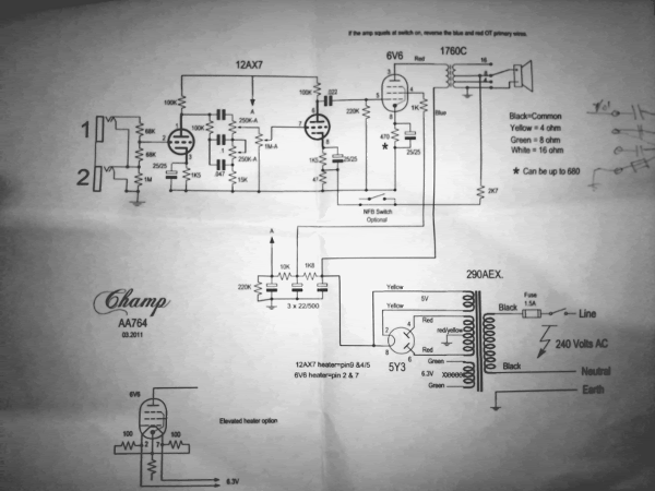 Had to take a photo - couldn't find the exact one I have online and I don't want there to be some subtle difference that will cause confusion. |
|
|
|
Post by reTrEaD on May 10, 2012 10:37:32 GMT -5
k, koo
I copied that to my hard drive and I'll scribble some notes on it, regarding ground layout. I noticed they do mention elevated ground. This is good. But they don't show where the loose end of that resistor connects to a positive DC voltage. Do they tell you in the text? One of the cathodes? Or better still, changing the bleeder resistor to two resistors in series?
|
|
|
|
Post by yakkmeister on May 10, 2012 19:56:37 GMT -5
None of the above. It's just what you see there.
the only text is at the top where is says to swap the OT primary wires if the amp squeals when you turn it on.
I should also mention that the front panel has been moved.
The amp sit on the bottom of the cab while a control plate is mounted at the top. To reduce the number of wires between the two I have run a wire from the 12AX7 Pin 7 into the control panel and another from the junction between the un-marked cap and the 100k resistor back to the 12AX7 Pin 1. A third wire takes a collected signal-return-earth back to the grounding scheme. All of these wires are solid-core, coax. The shield has been attached to the control panel and the backs of the pots and will be returned to the chassis. No signal is being sent through these shields.
|
|
|
|
Post by reTrEaD on May 11, 2012 21:19:58 GMT -5
Okay yak-man, this is the basic concept of star ground with subordinates. The star should be obvious. Things to note: Jacks are insulated from ground. The star could be a bolt in a convenient place in the middle of all the action. Long bolt with a nut holding down against the chassis. The wires going to the star have a ring eye crimped on them. The rings are stacked on the bolt and a second nut fastens them down.
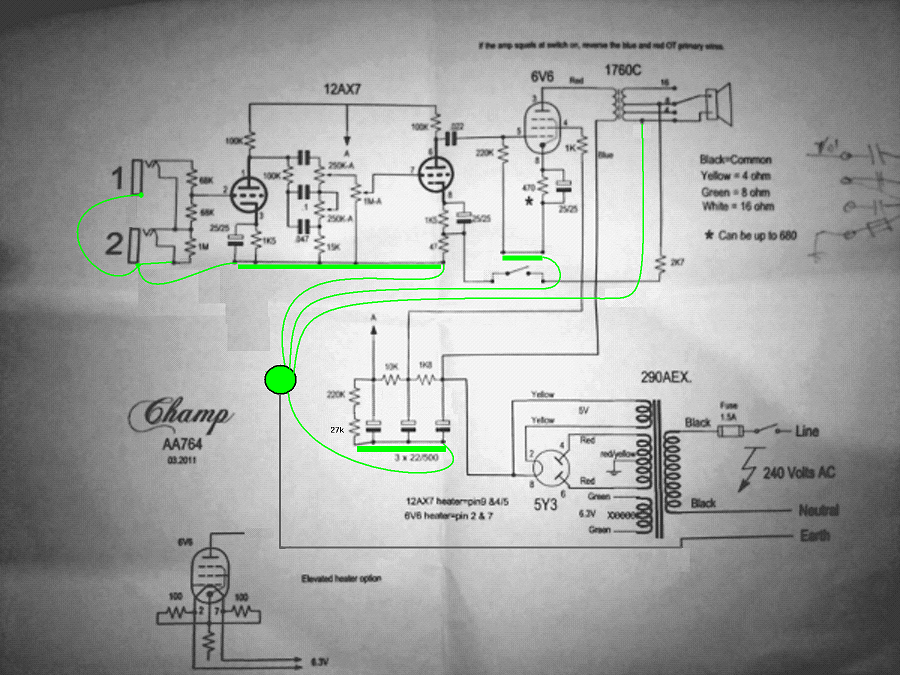  I included a 27k resistor so you will have roughly 50v DC to elevate the heaters. If the filament winding of your PT has a center tap, you won't need the 100 ohm resistors in the inset drawing. I'd suggest reading up about paralleling small capacitors in parallel with the electrolytics. I think this is a good idea. I just noticed that I forgot to draw the red/yellow of the PT going to the star. I'm sure you would have figured that out. Are you using an eyelet board or a turret board or point-to-point wiring? |
|
|
|
Post by yakkmeister on May 11, 2012 22:57:04 GMT -5
+1 for all the work! Eyelet board. The power supply section is on turret-board in a dog-house style config. I am a little bit constrained in this build as the guy I got the kit off had built the power supply section already (I think he expected I would kill myself ... ). The heater wiring is done as per the inset - I noticed that the resistor in the center could correlate with the bias resistor and research seemed to confirm this. There is no center-tap so I believe that this bias resistor is also acting as a fake-center. I have left the cap over this resistor also. The heater wiring then heads around the perimeter of the chassis and hooks into pins 4 & 5 of the 12AX7 (no connection to pin 9) to wire up the heaters in series for a 12.6V total. Research has suggested this is quieter due to less current draw. There's obviously more to it but I can't remember off the top of my head (and you'd already know anyways). How important is that new 27K resistor - It will take some serious rejiggering to get it in there (I don't mind doing it, however). Also, what rating resistor should this be? There is a pretty big solder-lug bolted to the chassis where the red/yellow wire from the pt is soldered. This is then connected to the power-cord socket at the center "E" terminal. This corresponds to your modified drawing pretty well. The big solder-lug is, however, full. I elected to connect the earths to the -ve side of the cap from which that section of the circuit draws power. IE: 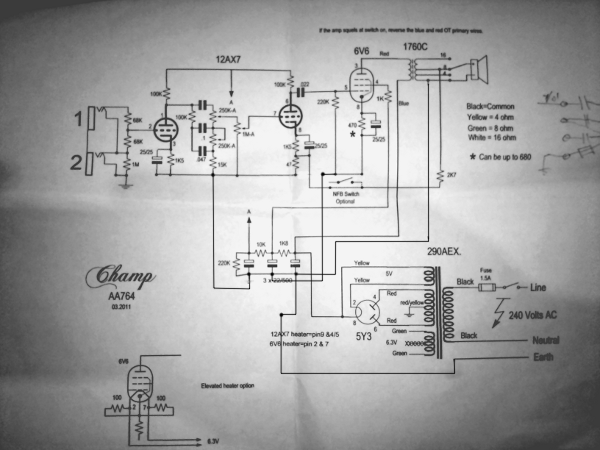 I just noticed that I forgot the input wiring ... I have wired it up as you have drawn and the earth connects to the same earth as the volume/tone section, as you have drawn. Ok - Going to read this now ... So that's more confusing than I ever expected ... It would seem that frequency response is supposed to be improved by the bypass however as many people agree also disagree. I could always add the bypass later - I assume this goes over the power-supply caps? |
|