|
|
Post by sumgai on May 11, 2012 23:44:45 GMT -5
The only fallacy I see going on here is trying to use a schematic to depict an assembly procedure.... that's a Romper Room No-No!  The whole idea of a schematic in the first place is to weed out any reference to "the real world" in terms of physical layout. Which then makes it obvious why we have layout diagrams, and why Fender supplied one with every schematic - sort of a 2-for-1 deal. Here, try monkeying around with this for awhile:  BTW, the "clone" diagram shows Inputs 1 & 2 reversed - Jack 1 should send the incoming signal through both 68KΩ resistors, whereas Jack 2 should only use one of them. Other than that, though, this looks like a pretty close reproduction of a Leo-authorized drawing. HTH sumgai |
|
|
|
Post by yakkmeister on May 12, 2012 0:46:52 GMT -5
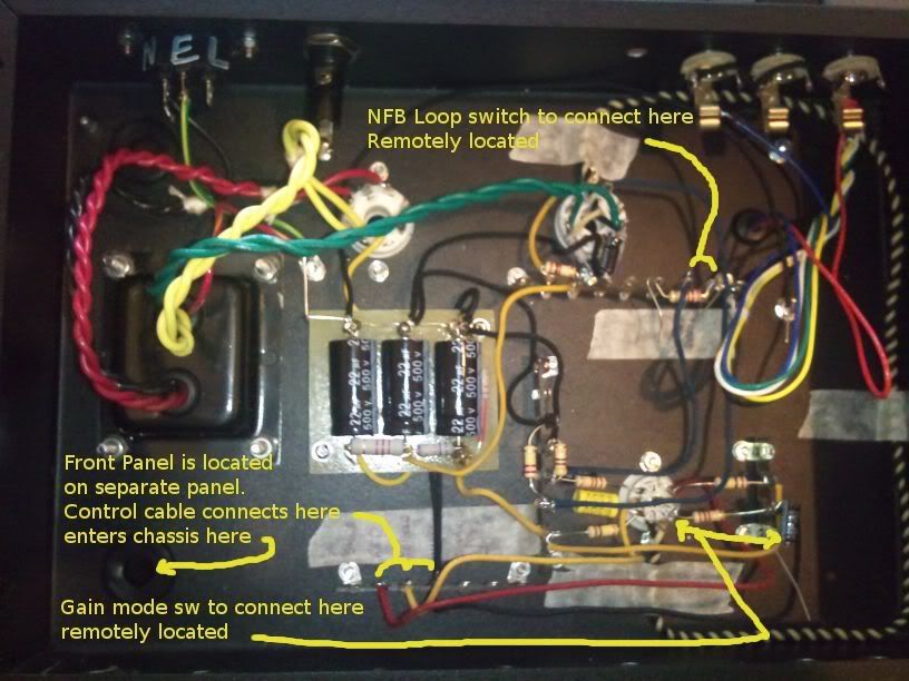
Sumgai, I wish I had something that simple to work off. The layout diagram / wiring diagram I have is next to impossible to read and looks nothing like that one. I have pretty much been wiring this thing straight off the schematic.  That is what I have actually done at the time of writing. Not the neatest thing in the universe ... but not too bad for a first go. NB: The gain switch connects to a cap that seems to be attached to a ground lug - yes it's a ground lug, no it won't stay there. I will be attaching that cap directly to the cable or something. The OT is mounted but not wired in, nor is the NFB switch or loop wired in. |
|
|
|
Post by sumgai on May 12, 2012 12:59:41 GMT -5
...... The heater wiring then heads around the perimeter of the chassis and hooks into pins 4 & 5 of the 12AX7 (no connection to pin 9) to wire up the heaters in series for a 12.6V total. Say what?  Don't tell me that New Math has finally taken over your schools too, like it did here...... Well, it'll be quieter all right, but not for the reasons you've espoused so far..... Yeah, it's that "more to it" that's gonna getchya.  Have you vetted that 12AX7's filament wiring with upside-down reTrEaD? I mean closely? sumgai |
|
|
|
Post by reTrEaD on May 12, 2012 20:05:07 GMT -5
The heater wiring is done as per the inset - I noticed that the resistor in the center could correlate with the bias resistor and research seemed to confirm this. There is no center-tap so I believe that this bias resistor is also acting as a fake-center. The cathode resistor for the 6V6 is indeed what is being shown in the inset. The two 100 ohm resistors create a "fake center". So the heater circuit "floats" on the same DC voltage at the cathode of the 6V6 (roughly +20v). Since this is more positive than the cathodes of the 12AX7, it prevents emission from the heater into the cathodes of the 12AX7. This is a case where "good enough" is good enough. Where convenient, I like to elevate the heaters so they are higher than the highest cathode voltage of any tube in the circuit. In this case, the 6V6. But most of the improvement is seen by elevating above the preamp cathodes. So no need to change if it adds a lot of difficulty. Skip the addition of the 27k resistor. I have left the cap over this resistor also. Good. Removing it would severely lower the gain of the final stage. The heater wiring then heads around the perimeter of the chassis and hooks into pins 4 & 5 of the 12AX7 (no connection to pin 9) to wire up the heaters in series for a 12.6V total. Research has suggested this is quieter due to less current draw. There's obviously more to it but I can't remember off the top of my head (and you'd already know anyways). You only have 6.3v available from your PT. You must wire the 12AX7 heaters in parallel. There is a pretty big solder-lug bolted to the chassis where the red/yellow wire from the pt is soldered. This is then connected to the power-cord socket at the center "E" terminal. This corresponds to your modified drawing pretty well. The big solder-lug is, however, full. I elected to connect the earths to the -ve side of the cap from which that section of the circuit draws power. IE: This is just the sort of thing that you don't want to do. The end of the wire connected to the (-) terminal of the caps is the dirtiest place in the ground circuit. Don't connect anything there, except the caps and bleeder resistor. If your big solder lug is full, add another. Hell, add three more if you like. Just stack them up and fasten them with the same bolt you already have. Point the lugs in different directions and it starts to look like a star.  Ok - Going to read this now ... So that's more confusing than I ever expected ... It would seem that frequency response is supposed to be improved by the bypass however as many people agree also disagree. I could always add the bypass later - I assume this goes over the power-supply caps? Yes, PS caps and also the cathode bypass caps. These are easily added at any time. That is what I have actually done at the time of writing. Not the neatest thing in the universe ... but not too bad for a first go. It's tidy enough, but running the heater wiring past the input jacks is a bad idea. Think 3 dimensional. Have the twisted pair come up vertically[/] from the 6V6 socket. Make a sharp right-angle bend at the height of the chassis' floor flange. Over to the 12AX7 and straight down to the heater pins. This might look a bit less tidy but it will be better in terms of hum.
The OT is mounted but not wired in, nor is the NFB switch or loop wired in.
After you are certain the primary wires are correct, trim them to length. |
|
|
|
Post by yakkmeister on May 12, 2012 21:45:13 GMT -5
...... The heater wiring then heads around the perimeter of the chassis and hooks into pins 4 & 5 of the 12AX7 (no connection to pin 9) to wire up the heaters in series for a 12.6V total. Say what?  Don't tell me that New Math has finally taken over your schools too, like it did here...... Well, it'll be quieter all right, but not for the reasons you've espoused so far..... Yeah, it's that "more to it" that's gonna getchya.  Have you vetted that 12AX7's filament wiring with upside-down reTrEaD? I mean closely? sumgai Thanks, Sumgai - all learning is good learning. I don't fully understand the heater-wiring configuration bit just yet - but give it a little time and I'll be good. |
|
|
|
Post by yakkmeister on May 12, 2012 22:55:01 GMT -5
The cathode resistor for the 6V6 is indeed what is being shown in the inset. The two 100 ohm resistors create a "fake center". So the heater circuit "floats" on the same DC voltage at the cathode of the 6V6 (roughly +20v). Since this is more positive than the cathodes of the 12AX7, it prevents emission from the heater into the cathodes of the 12AX7. Yeah - sounds like the ticket. Pretty neat idea, really. This is a case where "good enough" is good enough. Where convenient, I like to elevate the heaters so they are higher than the highest cathode voltage of any tube in the circuit. In this case, the 6V6. But most of the improvement is seen by elevating above the preamp cathodes. So no need to change if it adds a lot of difficulty. Skip the addition of the 27k resistor. Ok, Will do. If the amp is really noisy from heater hum, I guess I can add it later. Good. Removing it would severely lower the gain of the final stage. That is what I thought. You only have 6.3v available from your PT. You must wire the 12AX7 heaters in parallel. This part of it all really threw me. Now I will need to run, say, the black side (heater wire) to pin 9 and take a short wire from pin 4 to pin 5, right? This is just the sort of thing that you don't want to do. The end of the wire connected to the (-) terminal of the caps is the dirtiest place in the ground circuit. Don't connect anything there, except the caps and bleeder resistor. Oops? Thought I was really clever on that one too ... oh well If your big solder lug is full, add another. Hell, add three more if you like. Just stack them up and fasten them with the same bolt you already have. Point the lugs in different directions and it starts to look like a star.  Sounds good ... now to get some ... Yes, PS caps and also the cathode bypass caps. These are easily added at any time. I think I'll leave this for another amp - the next in line is geared more towards experimenting. This one is to have a good amp to play and to have something to point to and say "I can do it" if you know what I mean. It's tidy enough, but running the heater wiring past the input jacks is a bad idea. Think 3 dimensional. Have the twisted pair come up vertically[/] from the 6V6 socket. Make a sharp right-angle bend at the height of the chassis' floor flange. Over to the 12AX7 and straight down to the heater pins. This might look a bit less tidy but it will be better in terms of hum.
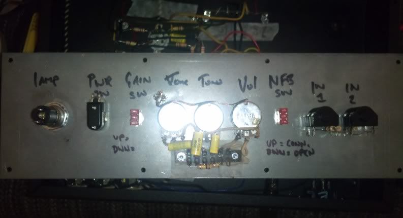
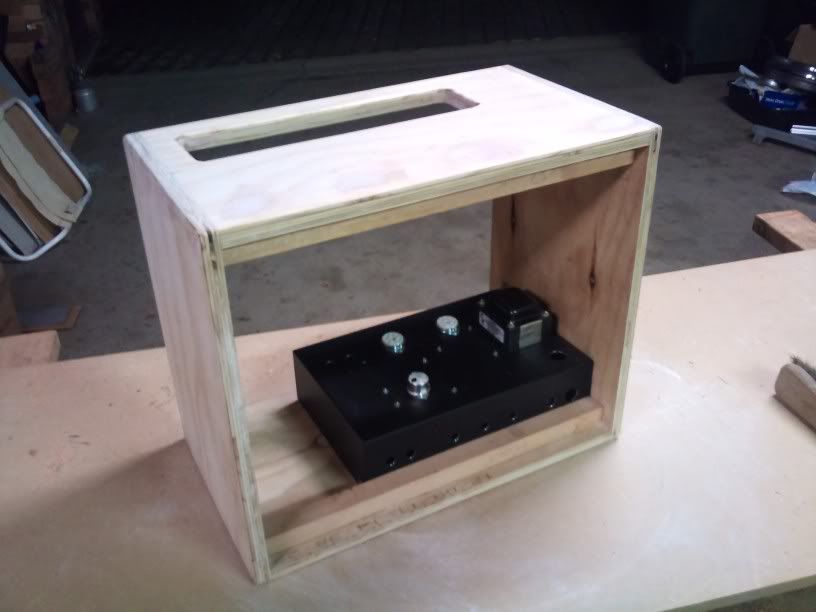
I understand what you're saying, but I already did the 3D thing in the opposite direction ... Also, the input jacks are located on a remote panel, meaning the heater wire is really, really far away from them. The wires that take signal from/to the preamp are all physically higher up than the heater wire. Those that cross it come straight up then go over. Should equate to the same thing, right? Great! Leave your primary wires full length. Initial tests should be done without the NFB. If all goes well there, then add the NFB. Be prepared to shut down in a big hurry if this screams when you power up the amp. If the PT primary wires are right, it will sound quieter and cleaner than without NFB. If they are wrong, it will oscillate HARD. After you are certain the primary wires are correct, trim them to length. The NFB is on a switch, remotely located, so I will have that advantage. I have wired in as much as I can without actually wiring the control cable now - the pilot lamp & power switch have their own, dedicated cable that will run separately to the signal stuff. Control Panel  Cabinet  The slot in the top of the cab is where the panel mounts to. |
|
|
|
Post by reTrEaD on May 13, 2012 8:13:14 GMT -5
Ok, Will do. If the amp is really noisy from heater hum, I guess I can add it later. If it's really noisy, look elsewhere. Elevating above the cathode of the output tube will only remove the last traces of hum in a nearly hum-free amp. This part of it all really threw me. Now I will need to run, say, the black side (heater wire) to pin 9 and take a short wire from pin 4 to pin 5, right? Yes. I understand what you're saying, but I already did the 3D thing in the opposite direction ... Also, the input jacks are located on a remote panel, meaning the heater wire is really, really far away from them. The wires that take signal from/to the preamp are all physically higher up than the heater wire. Those that cross it come straight up then go over. Should equate to the same thing, right? My bad. I saw those jacks in the upper right corner and thought they were the input jacks. The way you have the heater wiring routed should be fine. There are some things I like about amps with top mounted controls. But I prefer the way Leo did it. (occasionally he did get it right) Having the controls on one edge of the chassis facing up and having the tube sockets on the opposite edge of the chassis with the tubes pointing down has some definite advantages. Although soldering to the tube sockets is slightly more difficult, everything is local. Having a remote panel is something Gibson did in a few of their amps. I was never a fan of that. You're wise to be looking carefully at grounding techniques. This configuration lends itself to horrible hum problems if you do it "the easy way". |
|
|
|
Post by yakkmeister on May 13, 2012 18:10:52 GMT -5
I had planned to do it all in the one chassis but a single error meant I had to change a bunch of things and come up with some solutions. The remote panel was my solution - noting the massively long cable runs involved I realised there would be potential problems. Just what you need on your first build, right!  |
|
|
|
Post by reTrEaD on May 14, 2012 8:55:00 GMT -5
I'm almost afraid to ask what the error was that led you down this path.
|
|
|
|
Post by yakkmeister on May 14, 2012 20:34:07 GMT -5
It was a pretty silly error and nothing too scary.
When measuring out the box to easily cover in tolex and to actually fit in the twin 8" Jensens I have for this amp, the size of the amp itself managed to disappear from the calculations. When mocking up the baffle I noticed there was less than enough space for the speakers. By laying the box on it's side and mounting the amp facing up there was enough space on the baffle but the magnets were too close to the 6V6. In no position could I get a good combination of distance between magnets and valves with useful speaker position.
I came up with the idea of remote-location of the controls after a short thunking session. It solved those problems pretty neatly but introduced several of it's own. Since the box was already built (albeit without the hole for the controls) I figured it was best to go with remote control panel and shield the living crap out of it.
|
|
|
|
Post by yakkmeister on May 22, 2012 6:53:43 GMT -5
Powered up the amp today ... Holy Carp! It's noisy as balls! I am potentially going to dismantle the whole thing and re-do with a better layout. The current tag-strip setup is near impossible to work with. Just, FYI  |
|