|
|
Post by newey on Aug 11, 2012 20:25:05 GMT -5
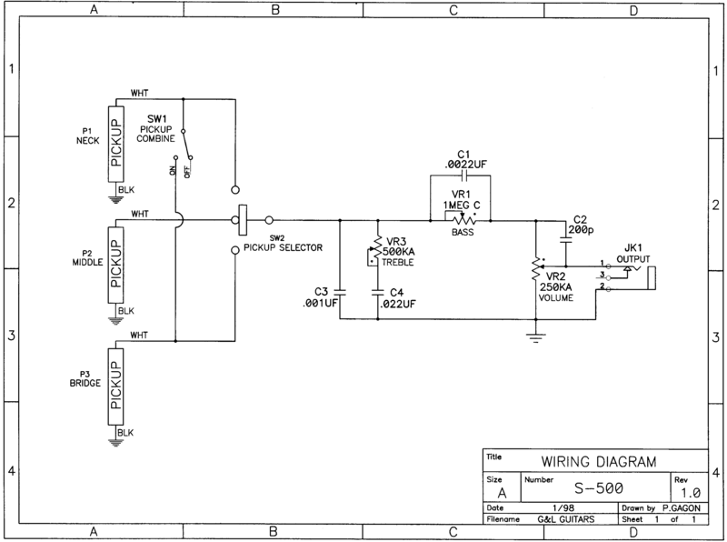
We've had a lot of recent discussion concerning the G&L Hi-Pass/Lo-Pass tone circuit, so I thought I'd post the original schematic of one of the G&L models, the S-500. This is re-posted from a post by ChrisK, and I include his (quoted) comments here as well. Also note the switching scheme, with the "neck on" switch plus the standard five-way toggle.  |
|
rolloman
Rookie Solder Flinger

Posts: 2 
Likes: 0
|
Post by rolloman on Nov 4, 2015 13:00:13 GMT -5
On the G & L schematic I want to make sure I get the pots wired in correctly. What significance does the small dot have? Is that pin 1, 2, or 3?
|
|
|
|
Post by reTrEaD on Nov 4, 2015 17:24:09 GMT -5
The dot indicates the clockwise end of the rotation.
|
|
rolloman
Rookie Solder Flinger

Posts: 2 
Likes: 0
|
Post by rolloman on Nov 5, 2015 9:24:28 GMT -5
Thanks. I can see that now once I thought and looked about how the volume and treble pots would need to work resistance wise for more volume or more treble.
|
|