|
|
Post by newey on Mar 23, 2013 13:33:27 GMT -5
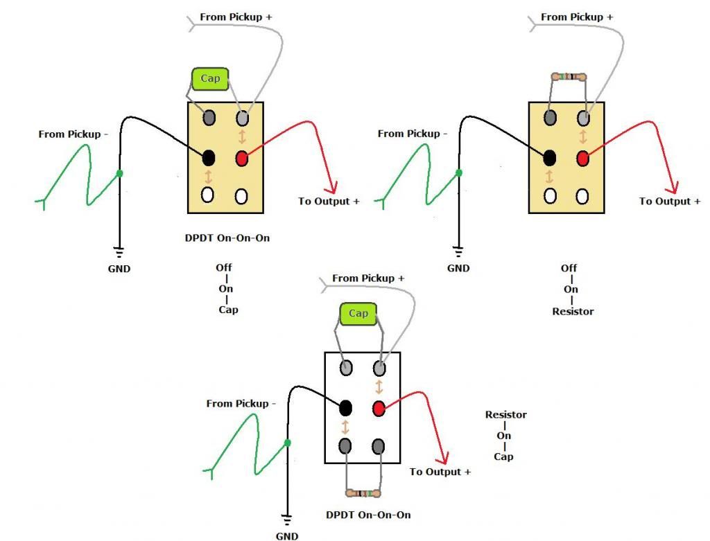
I've been toying around with various cap and resistor modules, based on DPDT On-On-On toggles. This is in connection with the seemingly-endless "Stealth Strat" build, which will use one or more of these modules for pickup control. Two of these are for pickup on/off, plus a fixed cap in parallel to ground (for a bass-y tone), or a fixed resistor (for a volume cut). The third offers both a cap position and a resistor position, with the pickup "on" normally in the center position. The first could be called an "On-Off-Strangle" arrangement. The second could be used to tame a pup which was overpowering others in combinations. The third is then a sort-of "Strangle-On-Tame" arrangement.  |
|
|
|
Post by sumgai on Mar 23, 2013 15:57:38 GMT -5
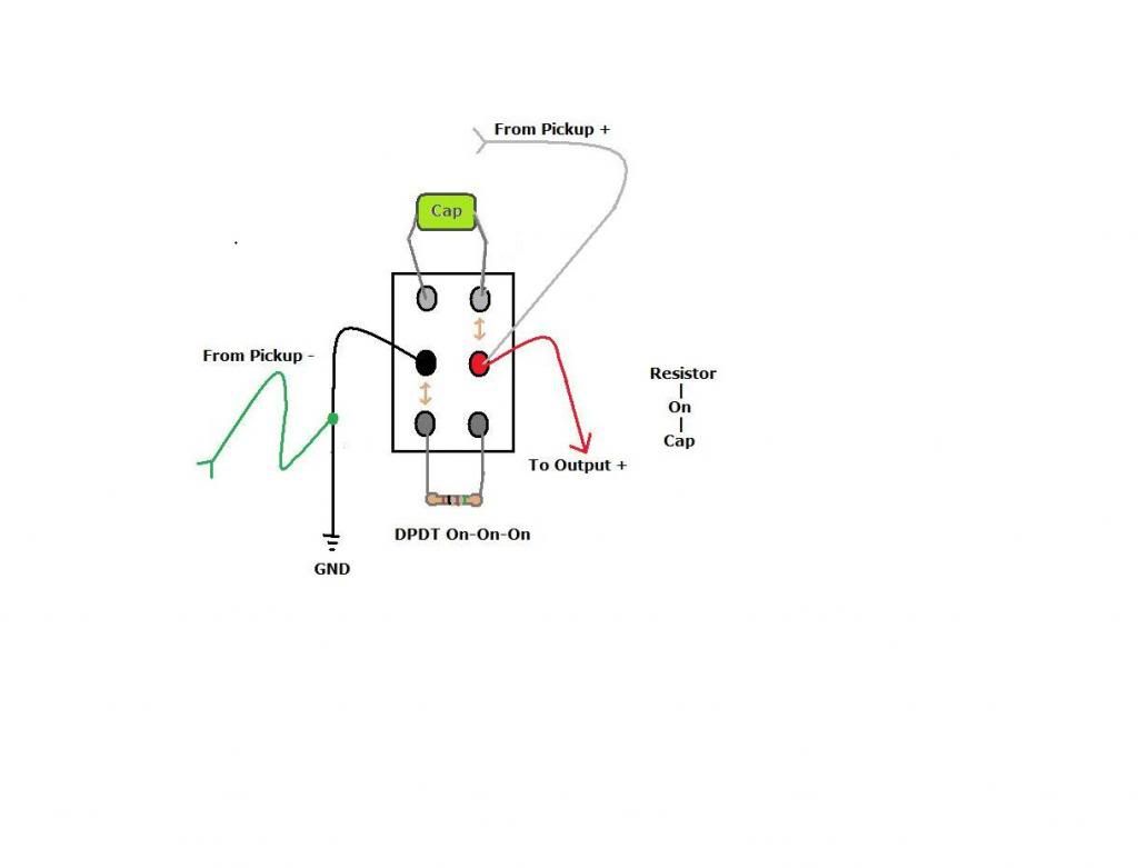
newey, Not a bad start...... I'm sure that most viewers will realize that your first two combos are over-complicated, but we all should remember that your goal is to be able to use a standard garden variety switch, easily available and fairly inexpensive. The goal of using the same kind of switch is always a good 'un, both from a design and from a stocking standpoint. However, your third diagram has an issue - in the "Up" position, where we should see the Tame effect, we won't have an ouput signal at all, because the pickup 'positive' wire is connected in the same fashion as in the other two diagrams. The fix is easy - in order to have the pickup sound out in all three positions, merely move that positive wire to the same terminal as the Signal Out. In addition, that third wiring option can also use an on-off-on switch instead, should the experimenter wish to do so. In order to use the on-off-on switch in the first two options, an additional wire would be needed, and the selection positions would be rearranged. But all in all, a good module for future reference, congrats on that.  sumgai |
|
|
|
Post by newey on Mar 23, 2013 17:54:34 GMT -5
Oops- I saw that and meant to fix it, then forgot to do so before I posted it. Here's the revision.  |
|
|
|
Post by ourclarioncall on Mar 27, 2020 21:01:06 GMT -5
What software do folks use to draw these nice diagrams ?
|
|
|
|
Post by ourclarioncall on Mar 27, 2020 21:03:21 GMT -5
That was strange, after I commented I could suddenly see your images clearly but before that they were all blurry . Weird
|
|
|
|
Post by newey on Mar 28, 2020 7:04:33 GMT -5
These were just with MS Paint (the old 2D version). Don't know why the images were blurry for you.
|
|
|
|
Post by ourclarioncall on Aug 27, 2020 19:42:26 GMT -5
The one with the cap
Is this intended to be used on just one single coil pickup at a time ?
What would happen if you had two single coils on in parallel and you switched the cap on ?
I was thinking that for two pickups wired in parallel a cap has to be wired in series. But your cap is wired in parallel , so what would it sound like ? 🤔
|
|
|
|
Post by ashcatlt on Aug 27, 2020 20:02:04 GMT -5
Parallel Cap = lowpass
Series Cap = highpass
Doesn't much matter what they're parallel or series with.
|
|
|
|
Post by ourclarioncall on Aug 27, 2020 20:10:21 GMT -5
Parallel Cap = lowpass Series Cap = highpass Doesn't much matter what they're parallel or series with. My brain is a bit slow so I would have to ask these questions for it to make sense 😊 If I do this what will happen? 1. Two single coils wired in PARALLEL with a cap On one of the pickups wired in PARALLEL 2. Two single coils wired in PARALLEL with a cap On one of the pickups wired in SERIES 3. Two single coils wired in SERIES with a cap On one of the pickups wired in PARALLEL 4. Two single coils wired in SERIES with a cap On one of the pickups wired in SERIES Thanks ! |
|
|
|
Post by ashcatlt on Aug 27, 2020 20:25:12 GMT -5
1. Two single coils wired in PARALLEL with a cap On one of the pickups wired in PARALLEL In this case, all three are in parallel. The cap acts as a lowpass on both pickups, like a master tone control turned all the way down. Highpass on the one with the cap. Depending on the cap value, you might get a little more low end out of the other pickup, but I doubt you'd notice. Maybe some resonance at the cutoff frequency. ( ?? ) This we call "broadbucker" around these parts. The coil with the parallel cap is lowpassed, but the high end of the other coil bypasses that one, so you end up with something like Humbucker low end and Single Coil treble. It's...interesting... In this case, all three are in series, so it's a highpass on the whole signal. newey - did you ever implement these? The resistor parallel to the coil should act more like a tone control turned down a bit than a volume control. |
|
|
|
Post by ourclarioncall on Aug 27, 2020 21:38:15 GMT -5
ashcatltthanks Ash, very interesting 🤔🙂👍
|
|
|
|
Post by newey on Aug 28, 2020 5:24:45 GMT -5
No, never implemented yet. That project (and several others) still sit on my workbench, languishing for lack of time. Right around that time in 2013 is when my real-life work started to metastasize, from say 60-70 hours per week to more like 100. But, I renegotiated my deal as of the first of this year, cutting back to 4 days a week in the office and limiting the workload so I wouldn't be spending all my nights and weekends working- for a correspnding reduction in $$. The idea was to have some more "me time" to work on some of these projects . . . but then the whole COVID thing hit, and my "partial retirement" hit the skids, working from home is just less efficient for me, still no time for either playing or modding.  |
|
|
|
Post by newey on Nov 14, 2020 8:06:01 GMT -5
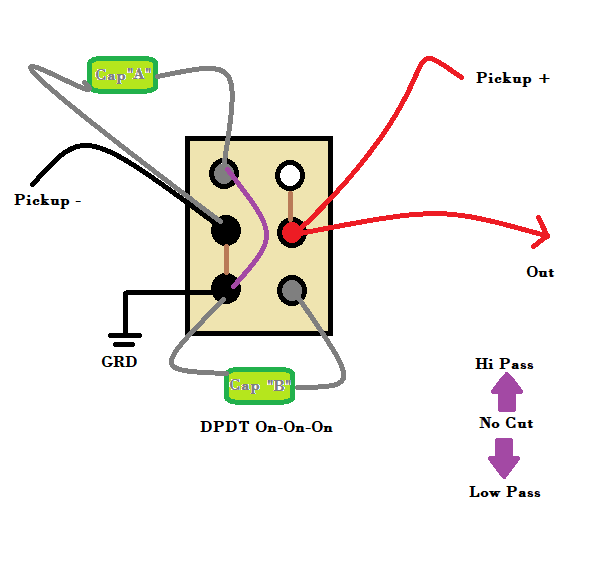
Parallel Cap = lowpass Series Cap = highpass Doesn't much matter what they're parallel or series with. Ash's statement got me thinking, sort of a "PTB on a switch":  I'm thinking this could be simplified somewhat, but darned if I can figure out how to do so. |
|
syddd
Meter Reader 1st Class
  
Posts: 62 
Likes: 10
|
Post by syddd on Mar 29, 2021 3:36:39 GMT -5
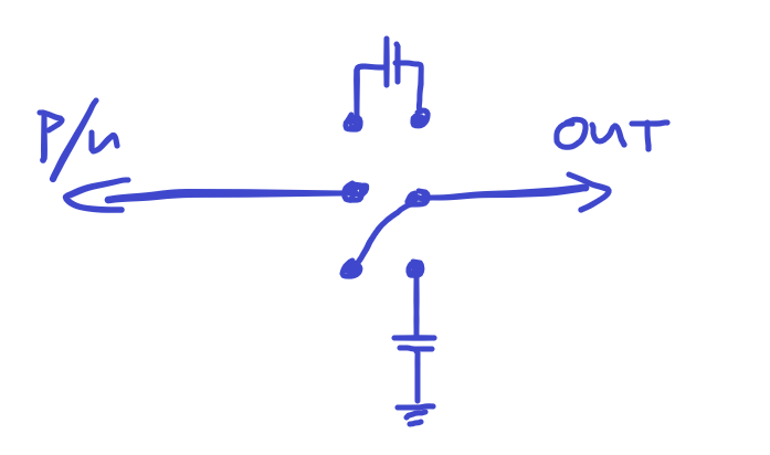
Parallel Cap = lowpass Series Cap = highpass Doesn't much matter what they're parallel or series with. Ash's statement got me thinking, sort of a "PTB on a switch":  I'm thinking this could be simplified somewhat, but darned if I can figure out how to do so. Hi Newey, Is this what you're trying to simplify to?  |
|
|
|
Post by newey on Mar 29, 2021 6:40:02 GMT -5
I was thinking the series cap had to be in series with the ground end, but now that I think about it, the order shouldn't matter in series, so we can put the cap on either end of the pickup. So, yes, your version simplifies things considerably by doing so.
|
|
|
|
Post by ourclarioncall on Mar 29, 2021 8:38:45 GMT -5
Greetings chaps, I just bought a drill for making pickguard holes . and am looking to get modding again. So after a long break I just started looking at this again the last few days
One point of concern was knowing if a switch I tried to design would work or not .
Now I’m wondering if it’s doing the same job as neweys last design and the recent poster that offered a modified picture (apologies I forget your name)
So can anyone tell me if my pic is doing the same thing ?
EDIT:
The context of My design is a brian may series parallel type wiring .
the idea was when the the wiring is in series mode to to have a cap for that , and then when in parallel , a cap for that. To save space , I’ve put them on the same switch .
|
|
|
|
Post by ourclarioncall on Mar 29, 2021 8:39:15 GMT -5
|
|
|
|
Post by newey on Mar 29, 2021 9:05:04 GMT -5
That should work, it's essentially the same as syddd's version.
|
|
|
|
Post by ourclarioncall on Mar 29, 2021 9:13:15 GMT -5
Thanks Newey
my brain needs a bit of help here ....
I’ve tried to draw out Sydd’s picture in a way I would understand it. Not sure if I have done it correctly?
Where is the ground wire from the pickup ? I only see the signal wire
I thought for parallel both the signal and ground wires from the pickup had to touch both ends of the cap?
is it because you don’t actually need to connect the pickup ground to the switch but can connect it straight to the output jack, and since one of the the caps is grounded , they will both meet at the output jack which is where they are going anyway
if I am making no sense I won’t be surprised!
|
|
|
|
Post by ourclarioncall on Mar 29, 2021 9:13:42 GMT -5
|
|
|
|
Post by newey on Mar 29, 2021 12:11:04 GMT -5
is it because you don’t actually need to connect the pickup ground to the switch but can connect it straight to the output jack, and since one of the the caps is grounded , they will both meet at the output jack which is where they are going anyway Yes, both go to ground, so it's all the same elctrically. |
|
|
|
Post by ourclarioncall on Mar 29, 2021 17:28:10 GMT -5
Thanks Newey, yeah that makes sense
how’s work? You still busy ? Poor stealth strat feeling lonely ? 😆
im just considering getting a bit stealthy with a guitar. Got a new drill , and a blank pickguard so I can maybe do some experiments.
|
|