shortie87
Apprentice Shielder

Posts: 42 
Likes: 0
|
Post by shortie87 on Sept 7, 2013 4:48:33 GMT -5
Yeah it made sense in the diagram, I just jumped the gun before I asked google! I'm had a look around and I can't find these for sale anywhere. To be honest, I doubt my soldering is at the level where I could manage that yet anyways!
|
|
|
|
Post by Yogi B on Sept 7, 2013 5:01:02 GMT -5
From what I can gather from the only two forum threads I could find on the subject, the one linked above and one over here, is that the doubled up version is/was only available direct from Eyb himself. |
|
shortie87
Apprentice Shielder
Posts: 42
Likes: 0
|
Post by shortie87 on Sept 7, 2013 5:11:15 GMT -5
Yeah I'd came across the one on gearslutz too, think it may just be easier to stick with the oak grigsby SS and use 2 P/Ps  |
|
|
|
Post by newey on Sept 7, 2013 5:51:06 GMT -5
Thanks for whipping that up, Yogi B! A nice job on the diagram, if only we could find the switch.
Shorty, if you still want B + M in the center position, you need the Superswitch to do that. A regular Strat switch can't do that, at least not if you want the middle pup at 2 and 4. There is a version of the EYB/Schaller Megaswitch that is internally connected to do N + B at position 3, but either way, you're buying a new lever switch.
|
|
|
|
Post by Yogi B on Sept 7, 2013 6:14:23 GMT -5
You're welcome Newey - also whilst I'm in the mood for whipping up diagrams, this is how I envisage John's option 5:  |
|
|
|
Post by JohnH on Sept 7, 2013 6:17:55 GMT -5
Lets go with option 5 and see how it works out, could always fall back to option 2. If I'm right, doing it this way would also negate the need for the superswitch, as the push/pulls will be doing the coil tapping? Here is version 5, in schematic form, which is the best way to start thinking through a circuit. As newey says, its still needs the super switch, or at least some special kind of switch, for the 5 way, and then two push push or push pull switches. 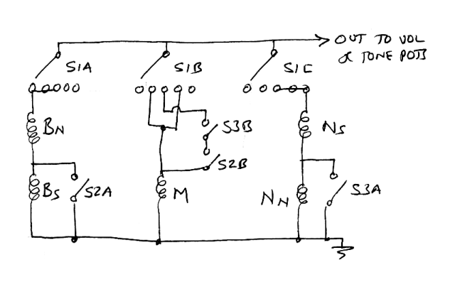 |
|
shortie87
Apprentice Shielder
Posts: 42
Likes: 0
|
Post by shortie87 on Sept 7, 2013 7:02:09 GMT -5
I'd be buying a new switch anyways, as the one thats in mine feels a bit cheap and nasty. So, Grigsby it will be! Its a shame that 8 pole isn't more widely available though!
John, thanks for the schematic, that makes much more sense to me so very helpful!
|
|
shortie87
Apprentice Shielder
Posts: 42
Likes: 0
|
Post by shortie87 on Sept 7, 2013 8:57:40 GMT -5
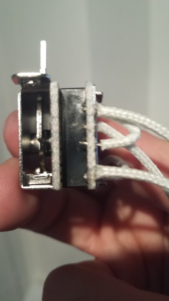
Hi guys, I've just been looking around at switches, and I've came across this: Ibanez 3PS1VLX91This is obviously a different layout to the standard super switches but is used in a lot of Ibanez guitars and is smaller, so I know it will fit, and should be tidier. They're also apparently indestructible. Pin outs are as follows: 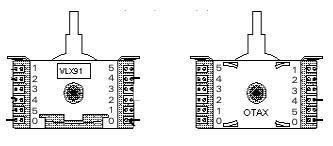 Should do the trick? |
|
|
|
Post by newey on Sept 7, 2013 10:29:17 GMT -5
The Ibanez OTAX switch will also do the trick. ChrisK's "Industrial Art" rendering shows you the internals, and can be cut/pasted for diagram use. 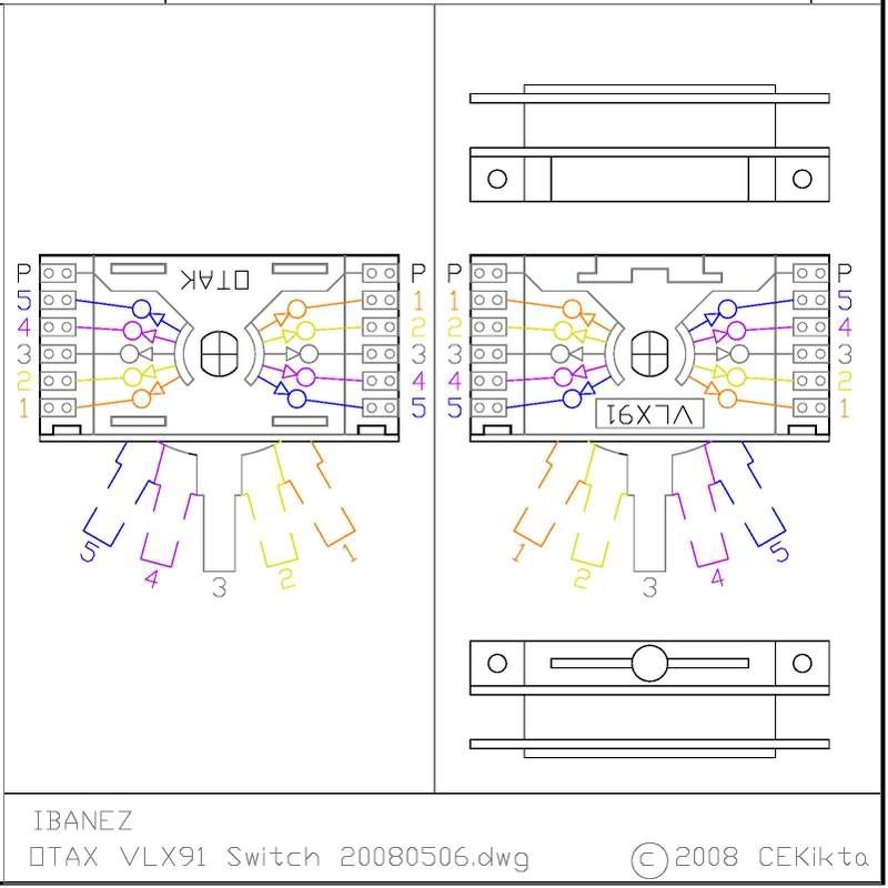 |
|
shortie87
Apprentice Shielder
Posts: 42
Likes: 0
|
Post by shortie87 on Sept 7, 2013 11:04:02 GMT -5
Thanks Newey, I've dropped those drawings into Visio so I'm all ready to go on the diagram, once I figure out how these switches work...
|
|
|
|
Post by newey on Sept 7, 2013 14:46:03 GMT -5
That's why I posted ChrisK's color-coded version. He has each position of the lever shown as a separate color, with the internal connections in the corresponding color. The Pole lugs, which are labelled as "0" in your picture are called "P" (for "Pole") in CHrisK's rendering.
So, for example, at position 5, the lever is in the blue position. The 4 pole lugs, 2 per side, each connects to its respective lug #5 at that position. At position 4 on the lever,the connections are shown by the purple lines, etc.
It is important to note that the lugs are mirror-imaged from right to left as you look at the switch, so it's 1-2-3-4-5 5-4-3-2-1. The same is true of a Superswitch, but in a horizontal dimension rather than vertical.
|
|
shortie87
Apprentice Shielder
Posts: 42
Likes: 0
|
Post by shortie87 on Sept 7, 2013 15:32:53 GMT -5
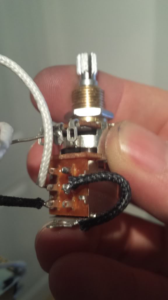
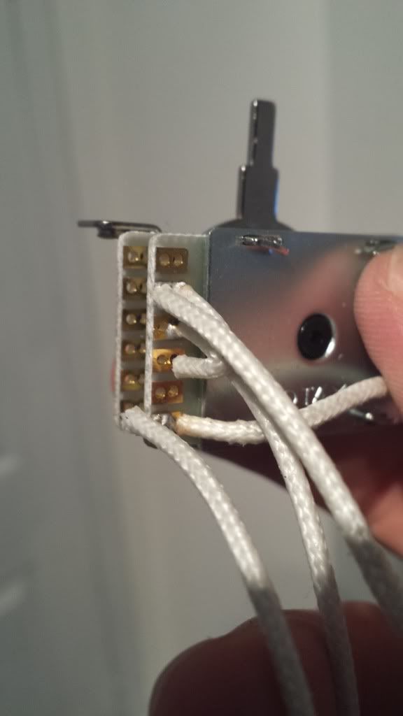
its more the DPDT switches on the push/pulls i'm struggling with I think, pretty sure i've got my head around the super switch thanks to the drawing you posted I've already started putting my diagram together at the switch end, the way i understand it should work, but once I figure out the P/Ps and how they switch, I'll try to get the rest done and throw it up here for you guys to find the holes in  |
|
|
|
Post by JohnH on Sept 7, 2013 15:56:04 GMT -5
its more the DPDT switches on the push/pulls i'm struggling with I think, pretty sure i've got my head around the super switch thanks to the drawing you posted This picture has some push/pulls, doing various things on an LP scheme: i731.photobucket.com/albums/ww316/JohnDHewitt/circuits/JHJPwiring1.gifI picked this image because they are quite nice graphic representations (which I borrowed from Runewalker).So you can see how the switch body is attached to the back of the pot. Switching is controlled by pulling and pushing on the pot shaft, but there is no in-built electrical connections between switch and pot, until you wire it up. It can do anything that a seperate dpdt switch can do There is one nice bonus though, beacuse the top of the switch furthest from the pot usually has a metal tag, and this is an easy place to solder ground wires to, much less tricky than the back of a standard pot (diagram shows some grounds to the pot, but these would go to this tag instead). There are two seperate switch poles each with three lugs, the poles being the two centre lugs. The standard position is pushed in, and in that state, the two middle lugs are each connected to the respective outer lugs furthest from the pot. For that option 5 schematic, in the default position, none of the switch connections will be made, so your diagram will use only the two middle lugs, and the two nearest the pot, so that all connections get completed when the shaft is pulled. |
|
shortie87
Apprentice Shielder
Posts: 42
Likes: 0
|
Post by shortie87 on Sept 7, 2013 17:18:35 GMT -5
If I'm understanding this correctly, I think the below should show the middle SC coming in from the left, grounded when the switch is off then allowed through when the switch is on... Possibly wrong! 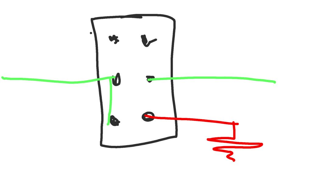 |
|
|
|
Post by JohnH on Sept 7, 2013 20:13:31 GMT -5
This is how I reckon you could wire up two pp pots, to fit in with the option 5 schematic:  I added som etreble bleed on the volume pot, optional. Also, you can see how grounds can go to the tabs at the top of the switch. Theres a need to consider wire colours and which coils to cut to, whicj is a further consideration. |
|
shortie87
Apprentice Shielder
Posts: 42
Likes: 0
|
Post by shortie87 on Sept 8, 2013 13:18:25 GMT -5
Thanks John :-) treble bleed is a good idea! I see what you mean about the tabs on the switches, looks a much easier place to solder to.
I'd probably use the slug coils, as that's what was recommended by bareknuckle. Wiring colours on the HBs are:
Black =start of screw coil
White = finish of screw coil
Red = start of slug coil
Green = finish of slug coil
|
|
shortie87
Apprentice Shielder
Posts: 42
Likes: 0
|
Post by shortie87 on Sept 9, 2013 5:51:27 GMT -5
Hi Guys, How hard would it be to modify this diagram to add another P/P to turn on/off the middle coil? I think that would give me everything I need... I'm struggling to come up with the diagram myself if I'm honest. 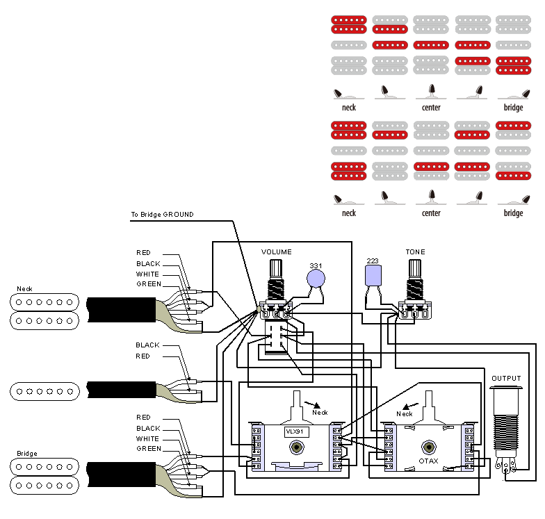 I know this will double up on a few options if I add the middle coil on another P/P, but it will also give me a few new ones I didn't have before. |
|
shortie87
Apprentice Shielder
Posts: 42
Likes: 0
|
Post by shortie87 on Sept 10, 2013 16:43:53 GMT -5
Well, I'm really struggling with this now, i've decided drawing out diagrams is beyond me at the moment, so I'm think of going for the diagram I'd found on Jemsite (some ibanez fanboy place) which I posted above. Would someone be able to glance a quick eye over it for me please, just to make sure its OK? John - Please don't think I've just dropped your option 5 idea. This is still my preferred option, but can I hell plan it out! This is what I've got HSH 2P/P Diagram
But, I'm convinced I've mucked it up somewhere! |
|
shortie87
Apprentice Shielder
Posts: 42
Likes: 0
|
Post by shortie87 on Sept 10, 2013 18:59:49 GMT -5
Hi John, Had a go at your switching scheme from a few posts back, I've missed off the 5 way, and i'm not sure what SIB LUG 1 is? Bit I think I'm on the right track...? White and green represent the centre tap on the humbuckers, white is hot on the middle. I've just noticed i've not earthed that, but no biggie for now. 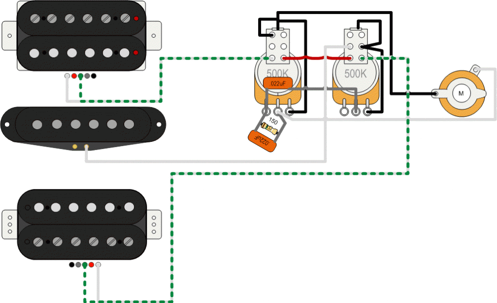 EDIT: I'm sat here at 2 am, staring at that schematic, and I think it's finally gone in! I'll have something by the end of play tomorrow, then hopefully, I can make a start! |
|
|
|
Post by newey on Sept 10, 2013 21:14:04 GMT -5
"S1B Lug 3" refers back to John's schematic a page back. He called the Superswitch "S1". He labelled the 3 poles of the Superswitch as S1A,S1B, S1C. So the third lug (center position) on the "B" pole.
On your diagram, note that the uppermost lugs (furthest from the pots)on John's diagram are all disconnected on both switches. You have connected one on the left-hand switch. That connection needs to move to the middle lug, as shown by John's diagram. Also be sure that all your grounds are collected together. If you use the grounding tab on one P/P for some, and the other P/P for other grounds, then the two P/P pots also have to be tied together, to gather all the grounds.
|
|
shortie87
Apprentice Shielder
Posts: 42
Likes: 0
|
Post by shortie87 on Sept 11, 2013 4:36:40 GMT -5
Right, I think I've got it... Got a bit confused with getting the middle pickup on in positions 2 and 4 while still getting the hot to the switch, so borrowed from Yogis diagram there. Think this should be good to go now? 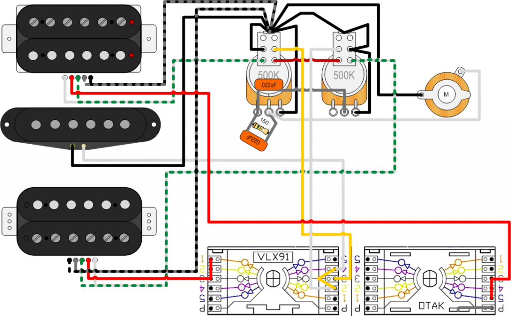 |
|
|
|
Post by newey on Sept 11, 2013 5:19:04 GMT -5
Shorty-
You haven't connected any of the "pole" ("P") lugs. These are what give you output from the switch. Look at JohnH's schematic again. He shows the switch as 5 circles, corresponding to lugs 1-5, and then above each 1-5 on each pole, there is a 6th dot with a lever attached to it. Those correspond to the "P" lugs and they need to be wired to the output as shown in John's schematic.
You seem to show one P lug wired to the body of the switch itself. If that is intended to show it grounded, the body of one of these import switches is not a good place to ground things. In any event, that should be going to output anyway.
|
|
shortie87
Apprentice Shielder
Posts: 42
Likes: 0
|
Post by shortie87 on Sept 11, 2013 7:17:18 GMT -5
Thanks Newey - Getting closer?  |
|
shortie87
Apprentice Shielder
Posts: 42
Likes: 0
|
Post by shortie87 on Sept 12, 2013 2:30:30 GMT -5
Ignore the ground from the unused Pole position. I've seen this grounded to the body on a few other diagrams I've seen around the net, but it doesn't need to be there, does it? Do I need to do anything with it if there is nothing using that pole?
|
|
|
|
Post by newey on Sept 12, 2013 4:44:44 GMT -5
Getting closer- but still not there.
All three pole lugs are connected directly to the volume pot hot. That doesn't mean three wires, you can daisy chain them.
But you have the red wires from the neck and bridge going to the poles. These wires instead go to their respective lugs on the 5-way switch. The middle pup wiring looks OK.
You then have the middle pickup's pole lug wired across to the other poles of the switch, and from there to the coil-cut switches. Again, it should go to the volume pot "hot" as shown on JohnH's schematic. You still have no output to the volume pot, the volume pot isn't connected to anything.
Understand that a P/P pot is just a regular pot with a switch stuck on its hiney. The switch and the pot are not electrically connected until and unless you wire them together for the purposes of a certain scheme. In this scheme, the two are kept separate.
The ground wire from the 4th pole is, as you note, superfluous, since nothing is connected to the other lugs of that pole. Grounding a lug doesn't ground the body of the switch, if that was the intention. There's probably no real need to ground the switch body, but if you want to do so, there's probably a metal tab on the side for that purpose, just as on the P/P pots.
|
|
shortie87
Apprentice Shielder
Posts: 42
Likes: 0
|
Post by shortie87 on Sept 12, 2013 5:15:54 GMT -5
Hi Newey, thanks for all your help with this How's this?  |
|
|
|
Post by newey on Sept 12, 2013 15:20:28 GMT -5
That looks better, with the understanding that the red wire actually connects the 3 pole lugs and isn't just lying across the one- I'm sure that's what you meant, but a dot at the junction to show a connection would make it clearer.
But, let's get another set of eyes before you start soldering. . .
|
|
shortie87
Apprentice Shielder
Posts: 42
Likes: 0
|
Post by shortie87 on Sept 12, 2013 15:57:07 GMT -5
That looks better, with the understanding that the red wire actually connects the 3 pole lugs and isn't just lying across the one- I'm sure that's what you meant, but a dot at the junction to show a connection would make it clearer. But, let's get another set of eyes before you start soldering. . . Edited, just for you Newey! Thanks to you all for your help, hopefully I'm there now! |
|
shortie87
Apprentice Shielder
Posts: 42
Likes: 0
|
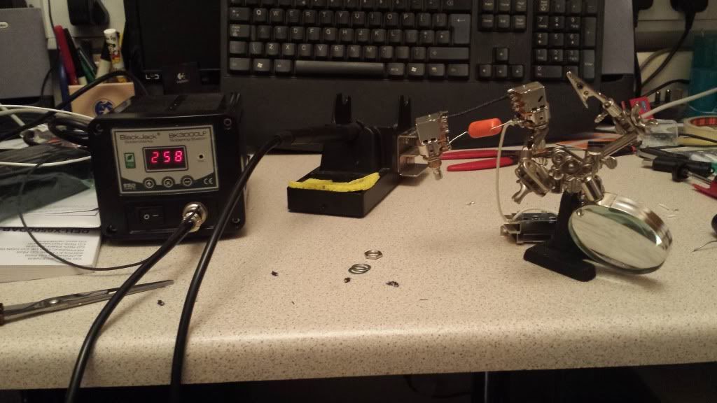
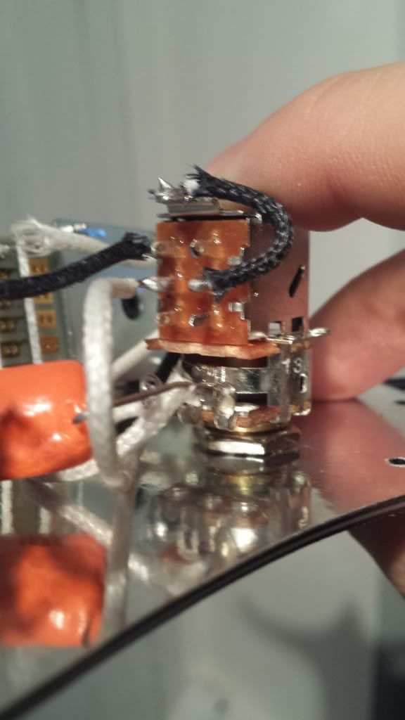
Post by shortie87 on Sept 13, 2013 8:51:48 GMT -5
So my Bourns pots have arrived today (which I got for the princely sum of £2.60 each from an electrical parts suppliers over here) along with a Switchcraft jack, so the only thing left to get before I start soldering are the pickups! I'll post progress pics and a few sound clips to compare before and afters, although I'll have so many more switching options when I'm finished, its not really a fair comparison!
|
|
shortie87
Apprentice Shielder
Posts: 42
Likes: 0
|
Post by shortie87 on Sept 13, 2013 15:57:48 GMT -5
|
|