bosox5150
Apprentice Shielder

Posts: 40 
Likes: 0
|
Post by bosox5150 on Dec 16, 2013 21:50:25 GMT -5
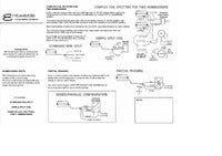
I would like to know if this is possible with these items, I have tried repeatedly but just seem to be stuck. I'm not asking for the help without not having exhausted myself trying first. I find and understand the abundance of diagrams out there. What I cannot wrap my head around or find any info on is the "what" needs to happen or be connected for a certain configuration but that's a whole other thread. The point I'm at is I've laid out the parts I have an un-connected diagram. If its possible with these parts and someone has the knowledge to fill in the connections from point a to b with Microsoft paint or however you do then I would be very grateful as I have completely hit a wall and have re-wired my axe 3 times now with no satisfaction.
the configuration is laid out I'm looking to achieve. I'm not concerned with using 1 or 2 DPDT pots its just whatever is do able. If its not possible then how about just the top configuration of coils and forgetting the bottom section with single coil modes.
here is what I'm working with and needs completion,
Attachments:
|
|
|
|
Post by JohnH on Dec 16, 2013 22:20:27 GMT -5
I would like to know if this is possible with these items, I have tried repeatedly but just seem to be stuck. I'm not asking for the help without not having exhausted myself trying first. I find and understand the abundance of diagrams out there. What I cannot wrap my head around or find any info on is the "what" needs to happen or be connected for a certain configuration but that's a whole other thread. The point I'm at is I've laid out the parts I have an un-connected diagram. If its possible with these parts and someone has the knowledge to fill in the connections from point a to b with Microsoft paint or however you do then I would be very grateful as I have completely hit a wall and have re-wired my axe 3 times now with no satisfaction.
the configuration is laid out I'm looking to achieve. I'm not concerned with using 1 or 2 DPDT pots its just whatever is do able. If its not possible then how about just the top configuration of coils and forgetting the bottom section with single coil modes.
here is what I'm working with and needs completion,
Hi bosox. The reason that it seems somewhat diificult is that it is actually impossible! At least with the parts that you have, and with the order of selections noted. But you can get those sounds. You could do a basic strat wiring, like the lower selections, but with full humbuckers instead of singles. Then use one switch to cut both humbuckers to singles, and the other to force the neck on. Out of those, you would have all the choices wanted, plus a few more. To do exactly wgat you suggest may be possible with a superswitch and a four pole toggle od a fender s1 switch..not syre though |
|
|
|
Post by newey on Dec 17, 2013 5:40:36 GMT -5
Bo-
Hello and Welcome to G-Nutz2!
JohnH is correct, can't be done with the parts at hand, unless . . .
What are the red and green indications on the 5-way switch supposed to mean? We're both assuming that you have a standard import-style 5-way Strat-style switch, since that's what the diagram looks like. But those colors make no sense if that's the case. Is this perhaps some sort of specialized switch?
As John mentioned, a Superswitch would do this, but there are also other specialized types of 5-way switches out there. If you have something other than a regular 5-way, then maybe we have spoken too soon. So, where did you find that, and what are the red and green colors representing?
|
|
bosox5150
Apprentice Shielder
Posts: 40
Likes: 0
|
Post by bosox5150 on Dec 17, 2013 10:39:43 GMT -5
The colors represent which pins are connected in continuity at each switch position, green being the 4 left pins and red being the 4 pins on the right. Its a Cor Tek 5-way lever found in many Ibanez guitars I believe. I also believe the center 2 pins are the commons or outs if you will but it is odd that there not constant and that each switch position does not change both left 4 and right 4 pins simultaneously and in some sort of even pattern like both sides of a 5 way fender switch or something.
I wouldn't mind skipping the single coil modes on the lower highlighted coil sheet if that opens up more room for connections. The upper sheet of modes is pretty common with the exception of position 3 usually has just the single coil or full neck & bridge but never have I seen an "all on". |
|
bosox5150
Apprentice Shielder
Posts: 40
Likes: 0
|
Post by bosox5150 on Dec 17, 2013 10:46:53 GMT -5
Here is the switch being used in another diagram if that helps, by adding a couple DPDT pots can't it open up room for the extra coils being on in the various switch positions?
Attachments:
|
|
|
|
Post by newey on Dec 17, 2013 11:15:29 GMT -5
Yeah, that was my point. So, the answer is, it may be possible with that switch. Have you verified with a meter that, in fact, those are the connections being made?
We have a posting of the Ibanez "OTAX" switch, which is another oddball 5-way, but similar to a Superswitch. I would like to include the info on this switch into our library of 5-way switches if you can indeed verify the switch logic as well as give us some photos to ID it.
As John noted, you can get all the sounds with 2 push/pull switches, but that will mean having to manipulate (potentially) 3 switches to access the various pickup settings you want.
If you just want the upper set of choices, with the "all on" setting in position 3, it would seem like the Ibby switch ought to do that. I think that could be done with a regular Strat switch also, although I haven't put pen to papaer on that yet.
|
|
|
|
Post by JohnH on Dec 17, 2013 14:58:17 GMT -5
Here is the a switch being used in another diagram if that helps, by adding a couple DPDT pots can't it open up room for the extra coils being on in the various switch positions?
That switch is a puzzle. The other diagram posted above is consistent with it being a standard import switch, as we first assumed. The left side makes the pickup selections and the right does the coil cuts. Any normal Strat switch can do that in an hss or hsh guitar. Meter tests will confirm how your switch works |
|
bosox5150
Apprentice Shielder
Posts: 40
Likes: 0
|
Post by bosox5150 on Dec 17, 2013 18:43:14 GMT -5
Ok I'm a big boy & can admit when I'm wrong or pull a bone head move, in this case both! I did verify the switch but only 3 positions and when they checked out I "assumed" it was the proper schematic. Having verified now with my meter "ALL" positions the switch makes more sense however I'm still lost. I updated the first attachment at the top of the post. Also here is an actual photo of the Cor-Tek switch It has a 5p 3 printed on the back . I have now verified the positions with a meter as shown in my 1st picture at the beginning of this post. Attachments:
|
|
|
|
Post by newey on Dec 17, 2013 22:57:54 GMT -5
OK, that clarifies that this is just an ordinary, garden variety offshore lever switch. I looked at trying to just do the top set of selections with the regular 5-way switch and I don't believe even just that is possible without a Superswitch. Actually, a "half-Superswitch" (2P5T)would work for just the first group. If you want to go with the coil cuts, then a full 4P5T Superswitch will be needed (plus a P/P). |
|
bosox5150
Apprentice Shielder
Posts: 40
Likes: 0
|
Post by bosox5150 on Dec 17, 2013 23:43:15 GMT -5
Thanks, I appreciate the help. I'm going to keep experimenting to learn myself all the possibilities. Understanding the switch helped clear up a bit of confusion as to why my earlier hook-ups where not working as I thought they should. After spending so much time analyzing things today I'm finally starting to grasp the "what's" and "whys" things are being hooked up in the places they are in any of the diagrams I come across.
As I stated in the beginning I could follow a diagram and understand where to solder wires but I wasn't clear why they went where they did and what was needed to make other configurations work. If I'm now grasping the concept correctly then what I'm seeing is basically the wiring creates 2 paths one which is all your hot leads for pickups you want on that switch where you choose but ultimately end up exiting the guitar through the center pin on your output jack, then the negative wires of the coils exit through the outer shield of the output jack. Everything in between is just figuring out what you want on/off at each switching point and making sure both signals are following through to there exits and of course being volume controlled. Does that sound about right? |
|
|
|
Post by JohnH on Dec 18, 2013 3:55:13 GMT -5
So how about what I suggested in post 2 above? it would be easy to do. |
|
|
|
Post by newey on Dec 18, 2013 6:06:09 GMT -5
That is "about right", but bear in mind that + and - aren't written in stone, since in some wiring schemes (i.e., out-of-phase)the two will swap places. Also. the "+" leads from the pickups won't always go to the 5-way selector first. There may be switches interposed, or pots interposed, between the pups and the selector switch.
John's idea has merit and is pretty straightforward. Use the 5-way to select the pickups as per usual Strat wiring, with the full HBs for N and Br. Use one P/P pot to cut both HBs to single coils. The other P/P pot could be used for a "bridge On" (or "neck on", your choice), which turns the bridge pickup on in conjunction with whatever else is selected on the 5-way. The then gives you access to the two "missing" Strat selections, namely N + B and N + M + B.
|
|
bosox5150
Apprentice Shielder
Posts: 40
Likes: 0
|
Post by bosox5150 on Dec 18, 2013 20:51:21 GMT -5
John could you connect the dots on my diagram to make that happen. I'm lost!
|
|
|
|
Post by JohnH on Dec 19, 2013 2:16:40 GMT -5
John could you connect the dots on my diagram to make that happen. I'm lost!
Sure ill help. But we may as well end up with a diagram that is as optimised as possible with the right wire colours. So some questions: What make and typee are the pickups? Covered or uncovered humbuckers? Do they have screw and slug coils (as a normal hb)? Place the humbuckers face to face, so screw coils face screw coils. Do they attract or repel? Place the middle pickup face to face with each humbuckers screw coil. Do they attract or repel? The next question may be to ask which wire colours relate to which coil, we can test, may be able to deduce from the above. All of that relates to getting best hum cancelling when combining in single coil modes. |
|
bosox5150
Apprentice Shielder
Posts: 40
Likes: 0
|
Post by bosox5150 on Dec 19, 2013 9:47:59 GMT -5
the diagram I've drawn is accurate for colors and coils as shown and labeled on the lower legend, currently there Gibson burstbuckers. the middle single coli is a stock infs3. the magnetism I'm not sure of but will pull them out & find out if your not sure after knowing the models now. I assume depending if they attract or retract you reverse coil polarity to wire them a preferred way? I have a few sets of pups and will probably change them a few times to see what I like best. Is there some general rule to having them push or pull on each other and reversing wires to match different magnetisms? I.E., if they attract use normal polarity or if they retract then reverse polarity or something like that?
|
|
|
|
Post by JohnH on Dec 19, 2013 15:54:25 GMT -5
Yes please I do need to know all those answers requested.:
Covered or uncovered? The reason is that in a covered pickup the screw coil sounds better on its own if coil cut. In an uncovered one, it has been said that the slug coil is better
I need to be able to know the relative polarities of each coil. The reason is that when combining pairs of coils, humcancelling but sounding in phase always comes from pairs with opposite polarity. We dont know what yours are. We dont necessarily need absolute norths and souths, we need relative polarifies. If they are installed, you probably dont need to remove them if you have another free pickup, a compass or a fridge magnef etc. Just work out if the middle pickup is the same or different polarity to the screw coil of each humbucker.
If we can get these answers, then the design has the potential to be perfectly optimised so every time you select two single coils they always minimise hum.
J
|
|
bosox5150
Apprentice Shielder
Posts: 40
Likes: 0
|
Post by bosox5150 on Dec 19, 2013 18:57:12 GMT -5
I'm going to go with this set of Entwistles instead now as I hooked up the burst buckers and not real thrilled.
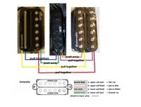
The Entwistles are double pole on the bridge and the neck has a metal bar on top coil and screw poles on bottom so IDK if this changes what magnetisms your looking for so heres a photo I took and traced out with labels what I found with each coils magnetism in relation to others. I also only know what ive included in the photo as for wiring, again it shows which coils are which colors and also lists a + & - so hopefully that's what your asking for. without a schematic how would one determine which wire is + & which is -? I know I can determine which wires show a resistance which tells me what pairs are coils, but how do you determine the polaritys of that pair?? I also included a schematic from there website which may help with knowing how they hook-up.
|
|
bosox5150
Apprentice Shielder
Posts: 40
Likes: 0
|
Post by bosox5150 on Dec 20, 2013 1:43:10 GMT -5
 Can you look at this example and read my analysis to let me know if I understand the "how" and "why" this does what it does in these 2 switch positions. If I'm not understanding it correctly could you explain it to me so I can figure out how to mock up my own designs correctly. Thanks in advance. Can you look at this example and read my analysis to let me know if I understand the "how" and "why" this does what it does in these 2 switch positions. If I'm not understanding it correctly could you explain it to me so I can figure out how to mock up my own designs correctly. Thanks in advance.
|
|
|
|
Post by newey on Dec 20, 2013 7:42:46 GMT -5
Bosox-
You were going along just fine there until you got to the part where you said:
"The green wire soldered to ground is also connected to the volume pot input thus completing the circuit . . . "
No. The diagram shows the grounds for both pickups, as well as the bare shield wires and the bridge ground, all being connected to the side of the volume pot's shell, not to one of the pot's lugs. If they were, in fact, connected to the volume pot's "input" and the "hot" wires were also connected there, the pickup would be short-circuited and you would have no output.
Ordinarily, it is the back of a pot shell (doesn't have to be the volume pot) that is used for a grounding point. The pot's shell is then also wired to the output jack sleeve (or "barrel"), so that you have the "hot" output going to the tip connection of the jack, and the ground to the sleeve. These two connections then are connected through the cable to the amp. The circuit gets "completed" only inside the amp (before everyone else jumps on that statement, yes I know that's an oversimplification of things).
The diagram just shows those wires to the side of the pot as a visual convenience, the author assumes it's understood to mean to the pot's shell.
One doesn't have to use the back of the pot as a grounding point, it's just convenient to do so. I never use the backs of pots, since most modern pots are now plastic inside and it's easy to apply too much heat trying to solder to the shell. I usually use a large washer, to which all the grounds are soldered. This is then held inplace to the side of the cavity with a screw, so that the cavity shielding also makes contact there. But you could just as easily leave the washer floating free with electrical tape over it to avoid inadvertent shorting.
Also, you will make yourself crazy if you number the 5-way switch connections as 1-8. Better to designate the lugs like this:
1-2-3-P P-1-2-3
This way, you can see what's really going on- there are two separate poles, each makes its own connections as the lever is moved. The "P" stands for "Pole", it is also often designated as "C" for "Common".
Or, if you want to be completely clear, since this is a 5-way switch, you could label the lugs as :
1-3-5-P P-1-3-5
That way, it can be visually seen what switch positions connect where. Positions 2 is just the combination of 1 and 3, while position 4 is the combination of 3 and 5. Note that a 3-way switch, like on a Tele, is exactly the same as a 5-way like you have, except that it doesn't make the internal connections for positions 2 and 4. So, by numbering it as 1-3-5, we can distinguish it from a 3-way lever switch.
Also, a pot doesn't have an "input" per se, the lugs as designated CW (clockwise) and CCW (counterclockwise, or "anticlockwise" for the British and Aussies among us). The center lug is called the "wiper".
|
|
bosox5150
Apprentice Shielder
Posts: 40
Likes: 0
|
Post by bosox5150 on Dec 20, 2013 12:17:17 GMT -5
Thanks Newey
that clears up some but the part that confuses me is still doing so. I am also familiar with labeling the pins in that fashion but for ease of reference in explaining which I'm referring to I will continue discussing them in 1-8 as labeled in the schematic. I added the output jack & perhaps if I left it in originally that path would have been clearer to me when I began to analyze it.
in position 2 when pin 7 & 8 contact causing the ground to white wire & cancels the red hot lead for the top coil, WHY does this not cancel the bottom coil if the black is grounded also, furthermore the green also goes to ground thus having the lower coils both wires black & green being at the grounding point and then to output shield with no lead through the volume pot.
1- Why does the ground shut the top coil and not the bottom?
2- How is it both the bottom coils wires green & black are ending up on the output shield without going out the tip?
3- What is the connection on the left tab of the pot? The connection from tab to pot side is this tab not an input like the right one? What does this do?
|
|
|
|
Post by JohnH on Dec 20, 2013 14:55:20 GMT -5
I'm going to go with this set of Entwistles instead now as I hooked up the burst buckers and not real thrilled.
The Entwistles are double pole on the bridge and the neck has a metal bar on top coil and screw poles on bottom so IDK if this changes what magnetisms your looking for so heres a photo I took and traced out with labels what I found with each coils magnetism in relation to others. I also only know what ive included in the photo as for wiring, again it shows which coils are which colors and also lists a + & - so hopefully that's what your asking for. without a schematic how would one determine which wire is + & which is -? I know I can determine which wires show a resistance which tells me what pairs are coils, but how do you determine the polaritys of that pair?? I also included a schematic from there website which may help with knowing how they hook-up.
OK, I think there is enough there to take a stab at your wiring. We should also do some work to check coil wire colours and phase, which you asked about. But taking your diagram that shows which coils attract and repel, and assuming that layout is also how the pickups are placed, and that the Entwistle logo tells us how you interpret top coil and bottom coil per their data: 1 When we combine the middle pickup with a single coil from bridge or neck, it should be with one of the outer humbucker coils in each case, because those were attracting the middle and so opposite polarity to middle 2 At the neck, the outer coil is the one with the bar, and it has the logo, so its the top coil so its black and white 3 At the bridge, the outer coil is the lower coil so red and green If we believe the Entwistle data, we can use it to get the wire colours for the humbuckers right, but we dont really know which way round to wire the middle. Taking these pairs of different magnetisms always gives either in-phase, hum-cancelling (good) or, if one coils wire get reversed, out of phase, humming (yuk). So to sort this out, and also check everything, lets test it. You have already been able to check which wires form a pair, so you can confirm that these pairs are red and green, and also black and white. If you connect these wire pairs to an amp and tap the polls lightly with a screw driver tip, you will get a thump, which should be stronger when you are tapping the pole of the wire pair that you have connected to. You usually get some thump when tapping the other pole too, because the coils are linked by a single magnetic field, but there should be enough difference to confirm, and check the data sheet for colours. Now to phase, and I like this test very much. Its the 'screwdriver pull off test' Read about it here, and there are several versions depending what gear you have. It works best with an analogue meter, or even better , a pc and some recording software, but also can be done with a digital meter. Screwdiver pull-off testThe key thing to know is that the output from a coil is dependent on changes in magnet flux, and in this test, the screwdriver is making a change in a single direction, as you pull it up, so it makes an electrical pulse in a single direction. You lay the tip quietly down on the top of the pole you are testing, let everything settle, then pull it up quickly and away in a single smooth movement, and you get a pulse. Lets say you are doing this with a meter, which has red and black leads. When you test each coil of the humbuckers, always put your black lead to the coil wires that will be nearer to ground, being the green (for the red green pairs) and the white (for the black white pairs). You will hopefully get consistent pulses for each of the four humbucker coils. These pulses might be + or -, that doesnt matter, but they should be all the same if their data is right. Now the key thing, do it for the M pickup, to work out which of its wires should go to ground (eg meter black lead), to get a pulse in the same direction as the humbuckers. As to the wiring diagram, the basic coil cuts will be to select the outer coils, so that positions 2 and 4 can be humcancelling with Nsingle+M or Bsingle+M. But if you use the other switch as well, which based on your info, I think should be 'neck on', by using spare switch poles, the other bridge coil will be selected for coil-cut, if you are in position 1 or 2. to get you Nsingle+Bsingle, or Nsingle+Bsingle+M. Here another thought. based on all of the above, the design is heading towards giving you the outer bridge coil as the Bsingle option. This one sounds a bit thinner than the inner bridge coil, and usually the inner one is preferred. Is it possible to mount your bridge pickup rotated 180 degrees? I would if possible, unless you want the twangiest Bsingle sound. It does not affect any wire connections that we are discussing. Could try this later if wanted. Lots of effort above in sorting out the combination single-coil settings, and in practice you'll probably may spend more time with other settings such as singles, humbuckers, or Hb + M. But these will all drop out in the wash and work fine, while the combo single settings have the potential to be better or worse depending on the care that goes into working them out, so we may as well get it right! John |
|
bosox5150
Apprentice Shielder
Posts: 40
Likes: 0
|
Post by bosox5150 on Dec 20, 2013 18:36:31 GMT -5
you are right about the order of the pups in my magnetism diagram (sorry for not stating that) and I do have a digital meter for testing.
so most of the figuring out magnetism and the phase stuff your referring to (which honestly will take me about 5 more reads before I grasp it) is all about determining the best way to setup for single coil modes? As I said in the beginning I'm not real concerned with the single coil modes as I mostly like playing metal like G'N'R, Metallica, Sabbath, AC/DC etc. and when I play that it sounds like a cat scratching at my strings anyway. But from what I've heard I like it better In HB mode then single coils & I actually like it better with the neck because it sounds more full and deeper than just tinny with no low end. that's why my original desire was for all full HB modes (LIKE BELOW). If including single coils is possible that's fine and I will do it as I'm sure as I develop my skill level I will appreciate that tone more, plus I just would like to know how as well.
this is my main desire,

what I was thinking and why I've been trying to understand the HOWS of diagrams so I could see if its possible, is to wire it up normally (I think its the norm) and use the pulls to activate the rest & give me the above. LIKE THIS, 
of course I have no idea if this will be possible until I understand how to create my own diagrams. But I'm definitely open to your edjucated suggestions and I really appreciate the time and help you and Newey have given me thus far! 
|
|
|
|
Post by newey on Dec 20, 2013 18:55:23 GMT -5
bo-
To answer the question you asked earlier:
The diagram uses DiMarzio colors. Red and black is the upper coil, green and white are the lower. So, at pos. 2, white is gounded, green also, so no output from that coil. On the other coil, red is to hot and black is grounded by the wire to the switch casing, so you get that coil.
Your Entwhistles of course differ, as John discusses above.
Your Question 2 is also answered by the above.
The lug (or "tab", if you will) is just shown as being bent over and soldered to the shell of the pot to ground it. As I noted earlier, all the grounds are collected there. Bending the lug over to the shell and soldering it there is a fairly standard technique in guitar wiring, you'll see that done in lots of guitars. You could run a separate wire from that lug to ground to accomplish the same thing- that's what I do when I'm not using the pot shell as a grounding point.
|
|
bosox5150
Apprentice Shielder
Posts: 40
Likes: 0
|
Post by bosox5150 on Dec 20, 2013 19:05:07 GMT -5
another question,
If I confirm the color pairs with my meter on an ohm setting it will only show a load if I have the correct pair right?
when I check the bridge red & green pair I get a reading of 6.16ohms but nothing on red-white or red- black so that confirms red/green as a coil does it not??
when I check the white/black (bridge) I get 6.09ohms
the neck red/green reads 5.22
& the neck white/black 5.33
now on the bridge when connected to my meter on red/green the ohms change between 5.10 to 6.90 if I tap the top coil, if I tap the bottom it jumps around 6.11-6.22.
does that confirm colors and coils?? I don't know about phase yet. |
|
bosox5150
Apprentice Shielder
Posts: 40
Likes: 0
|
Post by bosox5150 on Dec 20, 2013 19:14:07 GMT -5
thanks newey,
I understand the colors will differ, I was just trying to understand a diagram in general.
I guess just because the order was coming out of the pickup (in the diagram) red, white, black, green does not mean red-white are a coil and black/green another.
what still throws me off and I guess the diagram I took that from was WRONG, is that in position 2 it showed the bottom coil being active and the top coil off. but in fact it would be opposite.
That is from the second attachment I posted, the factory Ibanez drawing. Is it not correct?? |
|
|
|
Post by newey on Dec 20, 2013 22:21:03 GMT -5
The pickup as shown in the diagram has, it looks like, 2 sets of screw coils. So, we have no reference as to which one is the red/black coil. And, therefore, no reason to believe the diagram is wrong.
On a Dimarzio, the red/black coil is the North coil,which is the slug coil. Again, we can't tell from the diagram which is which. However, if the other coil is desired, there are two alternatives. First, assuming the wires are long enough to do so, you can rotate the pickup 180°. In the alternative, you can rewire the diagram so as to select the other coil. To do so, lug #7, instead of being grounded, is connected to the "hot" output. This then shorts the red/black coil to itself (since both are connected to hot) and instead gives you the green/white coil, as the green is permanently grounded, and white is now connected to hot.
|
|
bosox5150
Apprentice Shielder
Posts: 40
Likes: 0
|
Post by bosox5150 on Dec 20, 2013 22:43:38 GMT -5
does north and south coils not mean top and bottom? sorry to ask so many ?, I'm just really trying to understand how & why hook-ups work the way they do.
|
|
|
|
Post by JohnH on Dec 20, 2013 23:12:54 GMT -5
does north and south coils not mean top and bottom? sorry to ask so many ?, I'm just really trying to understand how & why hook-ups work the way they do. On your humbuckers, you will have a north and a south every time. Entwistle appear to have decided to refer to top and bottom, but there's no telling which is north or south from that. Other makers talk of slug and screw coils, but you have two screw coils! So lets just work from first principals. With the tests you are doing, we could work out wiring for completely unknown pickups from different makers, with random colours. We just have to sort out which wire colours go with which coil. Which way to connect them so they are all in phase, and which pairs can cancel hum together, and you are almost there. tAnd the tests wil confirm and extend the data that you have. |
|
|
|
Post by newey on Dec 20, 2013 23:18:52 GMT -5
No, it refers to the polarity of the magnets. And manufacturers are not consistent with their nomenclature- one's South may be another's North. That's why John had you putting the middle pickup against each coil of the HB. Again, we don't care about absolute polarity in this circumstance, it's not important which coil is North or South- it only matters relative to another coil.
|
|
bosox5150
Apprentice Shielder
Posts: 40
Likes: 0
|
Post by bosox5150 on Dec 21, 2013 11:06:48 GMT -5
John did you read my 2 posts above with the configs I really would like and if its possible in the manner I've shown. also the next post where I did the ohm test on the colored pairs? I assume I need to have them wired in to do the screwdriver test connected to the amp, the post said turn all the levels up, even volume? for wiring them up for that test should I just wire them in series red/whites together and set a side, each pups hot lead to its respective switch position and the grounds to vol pot side? Then plug it in, crank open my gains & do the pull of test with my meter connected to each coils pair? what is shortest path to ground about for each pair? that would be the meters black lead to leads on the pot side and the meters red lead on the coils hot lead at my switch correct? |
|


