travist
Rookie Solder Flinger

Posts: 11 
Likes: 0
|
Post by travist on May 23, 2014 3:24:12 GMT -5
Hello, I'm new to guitar wiring but not totally new to low voltage wiring. My guitar has 2 humbuckers and a piezo pup in the bridge. I like the idea of using a TRS output so I can run the magnetic pickups into one amp and the piezo into another amp. My plan is to wire the magnetic pickups through a 3 way toggle switch with a volume and tone. The Piezo will have a volume, maybe a tone and a little FET preamp circuit. I have looked and looked and done my homework so to speak but am having trouble finding this answer. I don't want to experiment and possibly blow something up. I am hoping the experience you guys have can tell me how I should switch between the magnetic and piezo pickups.
Thanks for your help! This is the diagram I created.  |
|
|
|
Post by newey on May 23, 2014 6:36:47 GMT -5
Are you referring to the grounding tab at the back of the toggle switch, opposite from the three switch lugs? If so, that is simply grounding the frame of the switch for noise suppression, it's not in the signal chain. It should be grounded to wherever your other grounds are collected, and then ultimately all those are tied into the TRS sleeve connection.
The three-way wiring is simple enough- mag "hot" to one side, piezo "hot" to the other, center lug to output. This switch goes "last in line", right before the jack (you may already have shown it this way, I can't seem to get your .pdf to open).
However, the issue you may have (I emphasize "may have", it might not be a big deal) is that, because you will be switching between an active circuit and a passive one, you may get an audible "pop" when switching between the two inputs. There are ways to avoid that, but I'll leave it to others to lay that out for you, as I'm no authority on active electronics.
Also, since you will be using all three connections of the TRS jack to carry signals, you can't use the ring lug to disconnect the battery when the cable is unplugged, as is often done in guitars with active electronics. This means never forgetting to switch the piezo circuit "off" when storing the guitar. However, there are jacks that are 4-conductor "TRRS" jacks, and using one of those would solve the issue.
|
|
travist
Rookie Solder Flinger
Posts: 11
Likes: 0
|
Post by travist on May 23, 2014 12:40:00 GMT -5
Thanks Newey, I posted the diagram I created
My question is if everything is basically funneling into this 3 way selector switch to choose "mag. - piezo/mag. - piezo" is there only one wire out of this switch? How do I turn this into mag out & piezo out to my TRS connector.
The magnetic pups are passive btw but I will have a 9-volt on my piezo preamp so good point there about on/off switch. Thank you.
Edit: Looking at my diagram and thinking about what you said, I'm thinking that the 3 way toggle switch for magnetic pickups will go to the other 3 way switch before it goes to the magnetic pups vol/tone and then out to the TRS connector. I'm guessing I can make that 3 way selector switch have 2 outs. One to magnetic volume, one to piezo volume. I will keep searching for wiring diagrams involving mag. & piezo pickup into 3 way switch out to trs connector.
|
|
|
|
Post by JohnH on May 23, 2014 15:07:20 GMT -5
Hi travist - The diagram that you drew has the piezo system completely separate from the magnetic, and that should be fine, with the 3 way switch just doing your mag options. Once you start to combine magnetic and piezo into a single signal however, it gets a lot more curly. The two signals typically have very different impedance and volume characteristics. Assuming the piezo has a preamp, then the output of that being lower impedance, can swamp the magnetic signal.
In practice, I think it is then better to make a simple preamp for the mag signal too, then you have two similar signals, and you can mix them. Given that as an intent, a pot to blend them instead of a toggle can be very nice. If you are building the piezo preamp yourself, then you will need some gain in the circuit to get the level up to match that of the mag. JFETs can do it. I did a few threads that may be off interest:
JFET buffers, with and without gain:
JFET buffers
This is a guitar where I combined a piezo made from a buzzer, with magnetic pickups:
Adding a piezo pickup
This one uses JFET buffer modules to wire up combinations of piezo and magnetic pickups:
Active pickup blender and volume module
For your jack and power switching, if you still want he separate outputs, it should be possible to get a TRS jack with a sepeate switch that could engage power when you insert the plug.
But maybe you are not intending to mix them in the guitar, and just want to switch them on and off? The Gibson toggle only has one pole, so would not be good for that. You could get and on/on/on mini toggle, which has two separate sides, and you can have both on in the middle position, without connecting them to each other. Or, a 3-way Tele switch could do it, since it also has two poles.
|
|
travist
Rookie Solder Flinger
Posts: 11
Likes: 0
|
Post by travist on May 23, 2014 17:30:29 GMT -5
Thanks for your reply John. I planned on keeping the piezo and magnetic pups completely separate using the trs jack. I want to split my guitar cable and run it into 2 different channels. I was under the impression that a jfet circuit for the piezo would bring the impedance down closer to the magnetic pickup and work better for amp and mixing board inputs. Right now, the guy who installed my piezo bridge just put a 471J (470pF?) cap between the 1st and 2nd lug of the piezo volume. I'm assuming this is to get rid of some of the highs of the piezo pup. I am using a normal 3 way pickup selector to switch between the magnetic and piezo pickups. But since I'm a guitar wiring noob and pretty much all diagrams I can find online are for a mono out, I am not sure how to come out of this switch with both seperate signals to individual channels of the trs connector. So in my diagram, the "3-way pickup selector" is the picture below. I believe this is the 3 way tele switch you spoke of. Middle position will be magnetic and piezo. I'm confused how to send the magnetic and piezo pickups to this switch and then have them both come out to their own individual channel on the trs connector. Do the volume and tone go after this switch? I do know the JFET should go after the volume/tone pots. Given what I described here, do you really think I should make a preamp for the 2 passive humbuckers? I don't want a blend pot. I want to either have it mag., mag & piezo or just piezo with their own volume controls. Typically it will always be in the middle position with both. Thanks for your time! I'm excited to start rewiring this guitar, but I'm waiting until I have everything figured out and diagrammed. 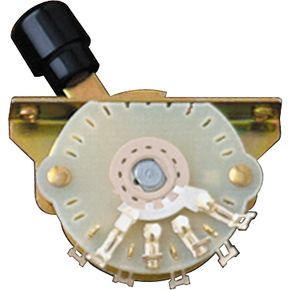 |
|
|
|
Post by JohnH on May 23, 2014 18:05:43 GMT -5
Ok..yes i only figured out what you meant when i added my last paragraph!.
So, no need for a buffer for the mag pickups.
that switch you posted above is fine. I can post a sketch later. Normally a tele switch has a wire joining its two poles, to go to a volume pot. Instead you will take each pole to its own jack connection. One from each switch side. On one side, lugs 1 & 2 will go to the mag output. On the other, 2 & 3 will connect to the piezo output.
Need to find the right jack. Also decide on a jfet vircuit. Without the preamp, and without worrying about tone, is it loud enough, or does it need a boost?
|
|
travist
Rookie Solder Flinger
Posts: 11
Likes: 0
|
Post by travist on May 23, 2014 18:49:50 GMT -5
That's great news John. That makes sense but I will wait for your sketch so I don't blow anything up. This switch is weird to me. It's hard for me to visualize the connections. There is a TRS jack already in my guitar. I think it came with my piezo bridge. I will consider the battery on/off switching though. I had a shop install the bridge and wire the pickups. They just put a volume knob on the piezo so I'm rewiring it because I want to be able to switch back and forth easier than turning down one knob and up the other! There were two JFET circuit's I was looking at. One was designed for a bass. Would that make a difference? This one was designed for a bass.This one seemed like a good one.As far as gain, I really don't know. As it is right now with that simple capacitor and volume knob, it sounds ok. I don't have the experience to determine that at this time. My thought was I wanted to balance the sound and make sure the impedance was correct. Unless you guys have some words of wisdom I will probably just start with this "basic" way and then adjust it later if I need. My Piezo bridge is an L.R. Baggs X-Bridge
My magnetic bridge is a Seymour Duncan JB Sh-4My neck pickup is some cheap Jackson pickup that I plan on changing soon. I was thinking of putting in a Gretsch Filtertron. If anyone has any insight about optimizing my wiring or sound here I'd really enjoy it. Thanks! |
|
|
|
Post by newey on May 23, 2014 21:59:54 GMT -5
John's right, you need a two-pole switch for the piezo-mag switching to keep the outputs separate. You just treat it like two separate switches connected to the same lever. One common lug is connected to the Jack tip, the other to the ring. Piezo connects to one pole at positions 1 and 2, mag connects to the other pole at positions 3 and 4.
|
|
travist
Rookie Solder Flinger
Posts: 11
Likes: 0
|
Post by travist on May 23, 2014 23:03:26 GMT -5
Oh that makes sense. So intead of the common outside lugs that are wired together, you don't connect them and instead send it to the output?
Do I put the volume before or after this switch? Thanks again!
|
|
|
|
Post by newey on May 24, 2014 5:29:02 GMT -5
Volumes (both piezo and mag)go before the switch. This switch will be last in line before the output jack. Yes, each output gets its own pole on the switch.
EDIT:Like this: 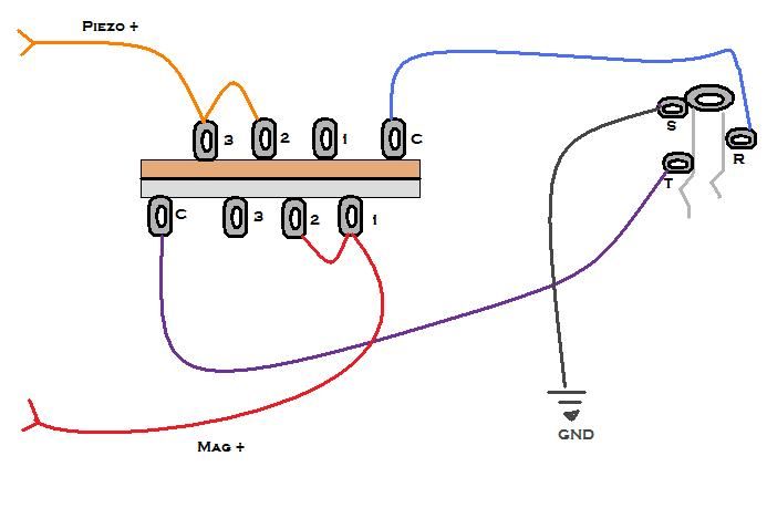 |
|
|
|
Post by JohnH on May 24, 2014 7:30:34 GMT -5
newey has done the diagram, sorry I didn't get to it today.
It might be worth connecting the unused lugs to ground, so that you have a very quiet off position for each side.
If you do the preamp, one of the modules I posted above 'active pickup blender and volume module' should work well. It is x1 gain, and I see tha Baggs says that the piezo bridge has similar output to a typical magnetic pickup. You can leave the pot off the board as shown and connect to the output of the three-way switch, right before the jack.
I've built this circuit several times, and it's designed to do this job. One of the best benefits is that you can use it to drive the line-in on a mixer to get a good full range signal from your piezo, through a PA system.
|
|
travist
Rookie Solder Flinger
Posts: 11
Likes: 0
|
Post by travist on May 24, 2014 10:34:13 GMT -5
Thanks you guys, I really appreciate it. I will use that circuit John, it sounds like a good idea. Thanks for making this circuit even better than I had in mind.
|
|
travist
Rookie Solder Flinger
Posts: 11
Likes: 0
|
Post by travist on Jul 16, 2014 12:41:55 GMT -5
Hello,
So I've been working on this diagram. I actually chose the Trey Anastasio diagram with 2 humbuckers, coil tap, phase & series/parallel switch. I decided to go with 2vol 2tone for the mag. pups.
Anyways, when I wired up the blade switch that chooses between piezo and magnetic pickups I get nothing in the middle position. The other positions work just fine.
I have it wired as Newey showed above. However, due to John's suggestion I wired the two "Dead" lugs together and connected them tp ground. (In Newey's diagram, Piezo #1 and Magnetic #3.) Was this wrong? The middle position should allow the magnetic signal to go to the tip and the piezo to go to the ring, but I get nothing.
Does anyone have any thoughts about this? Thanks
|
|
|
|
Post by JohnH on Jul 16, 2014 15:19:44 GMT -5
Maybe just check on your switch lug arrangement. Newey's diagram has the C common lugs lower left and top right, being the furthest two apart. But other switches can have them at the other end. With that type of switch you should be able to see how it is working to check that. The 3, 2, 1 lugs will always be in that order, but their respective C lugs could be to the left or the right of them.
|
|
travist
Rookie Solder Flinger
Posts: 11
Likes: 0
|
Post by travist on Jul 16, 2014 16:46:33 GMT -5
Thanks for the reply. I was wondering about that. I didn't think it matter which way you wired it. I was having difficulty following the path with this switch. I will just flip it all around and see if that works!
Thanks!
|
|
|
|
Post by JohnH on Jul 16, 2014 17:13:33 GMT -5
Ok..but note that spinning the switch 180° and then wiring to the same diagram makes no difference to a given switch. The issue to address is, mounted as it is, are the C lugs on the left and right or on the right and left on upper and lower sides.
|
|
travist
Rookie Solder Flinger
Posts: 11
Likes: 0
|
Post by travist on Jul 17, 2014 11:31:11 GMT -5
Haha, thanks. I meant flipping around the wiring. I was being flippant with my vocabulary!
|
|


